Assemble the Main Electronics
For this section you will need:
Electronic Components
- 7 10 cm female-female jumper
- 8 20 cm female-female jumper
- 1 40 pin header
- 1 5.5mm female jack connector
- 1 Raspberry Pi Pico
- 2 TMC2209 driver
- 1 Voltage regulator
Mechanical Components
- 6 M3 10mm screw
- 1 M3 25mm screw
- 8 M3 nut
Printed Parts
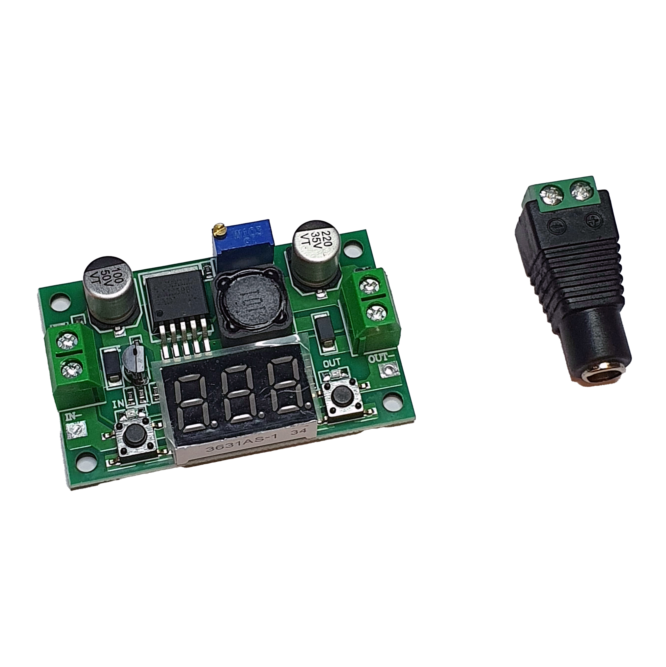
Step 1: Prepare the Voltage Regulator Circuit
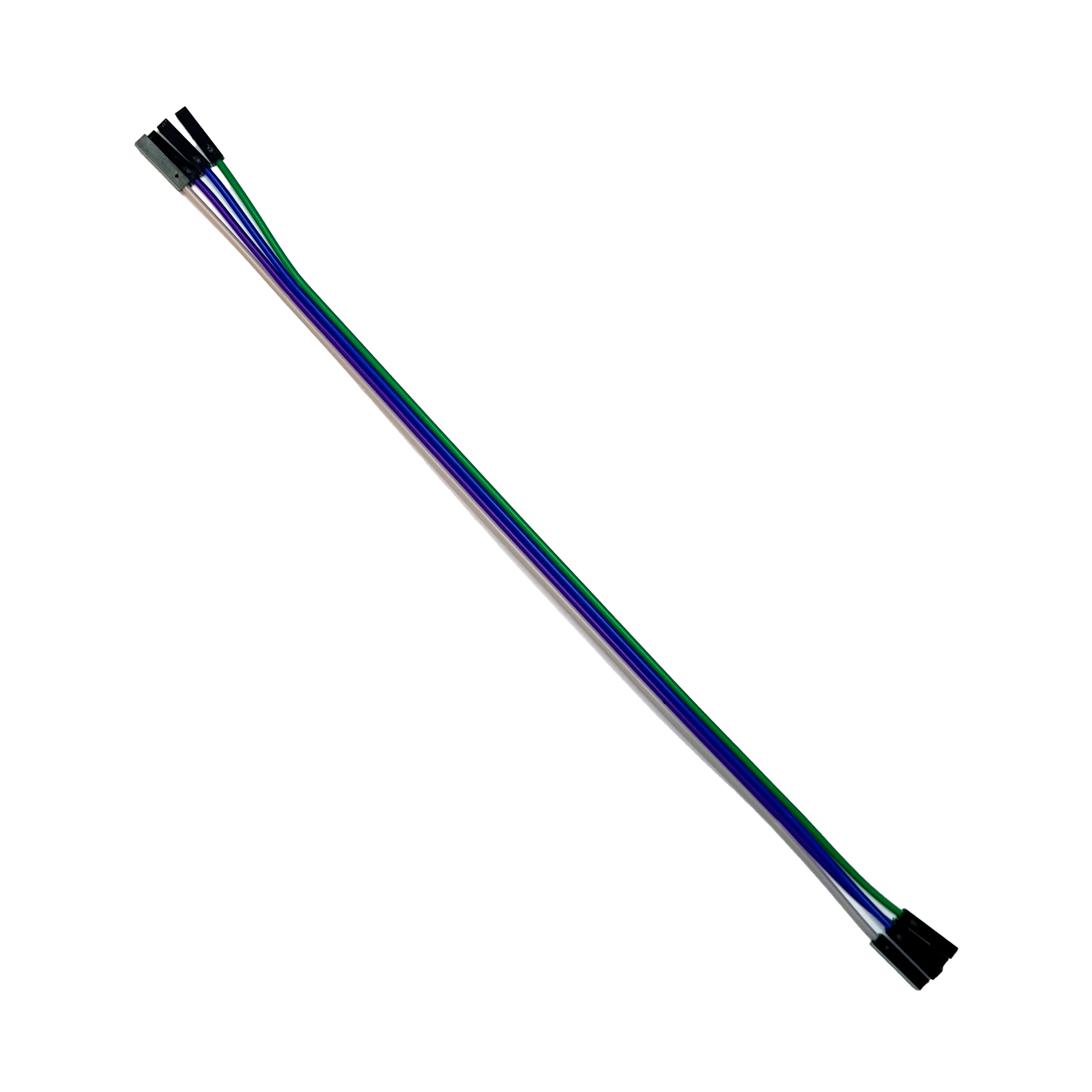
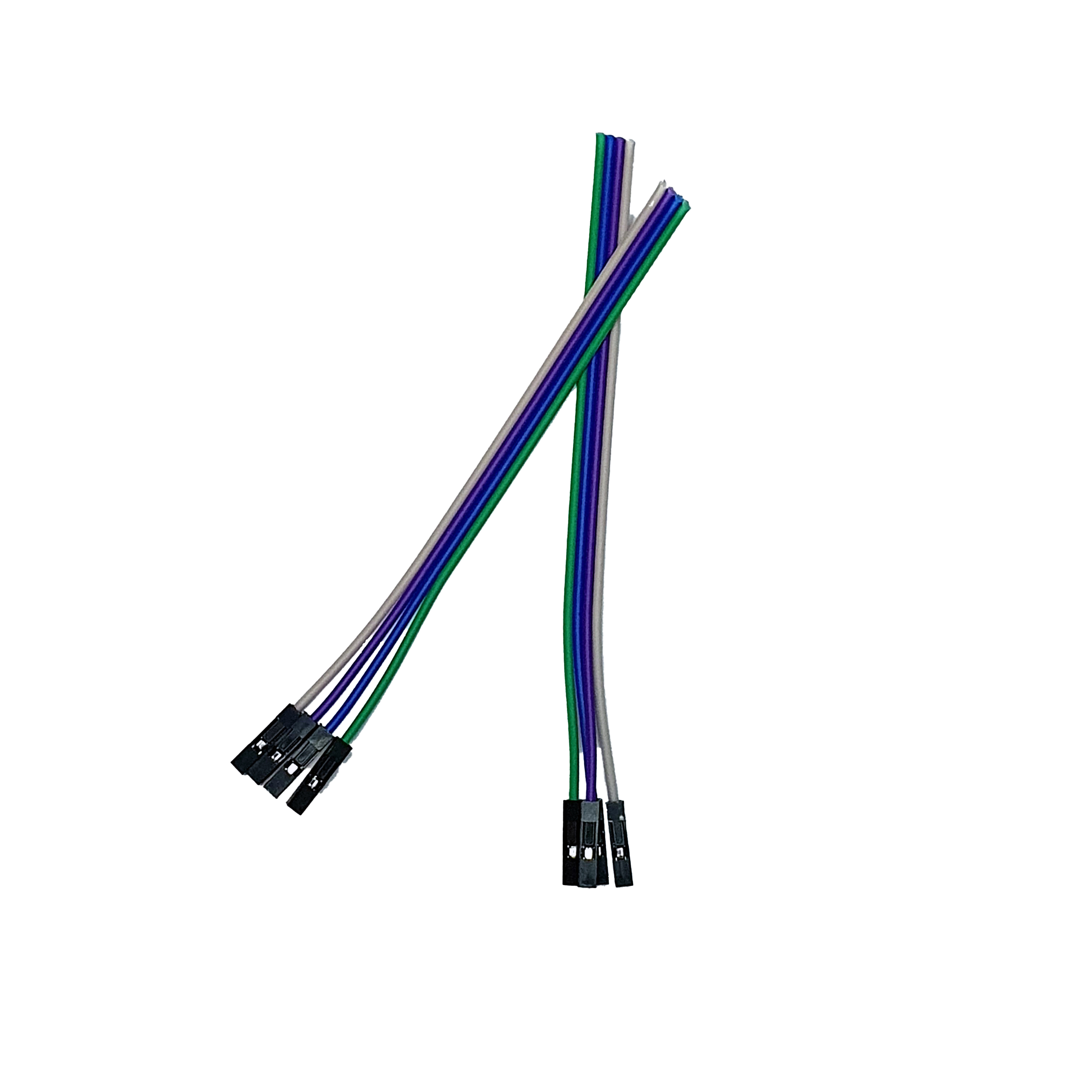
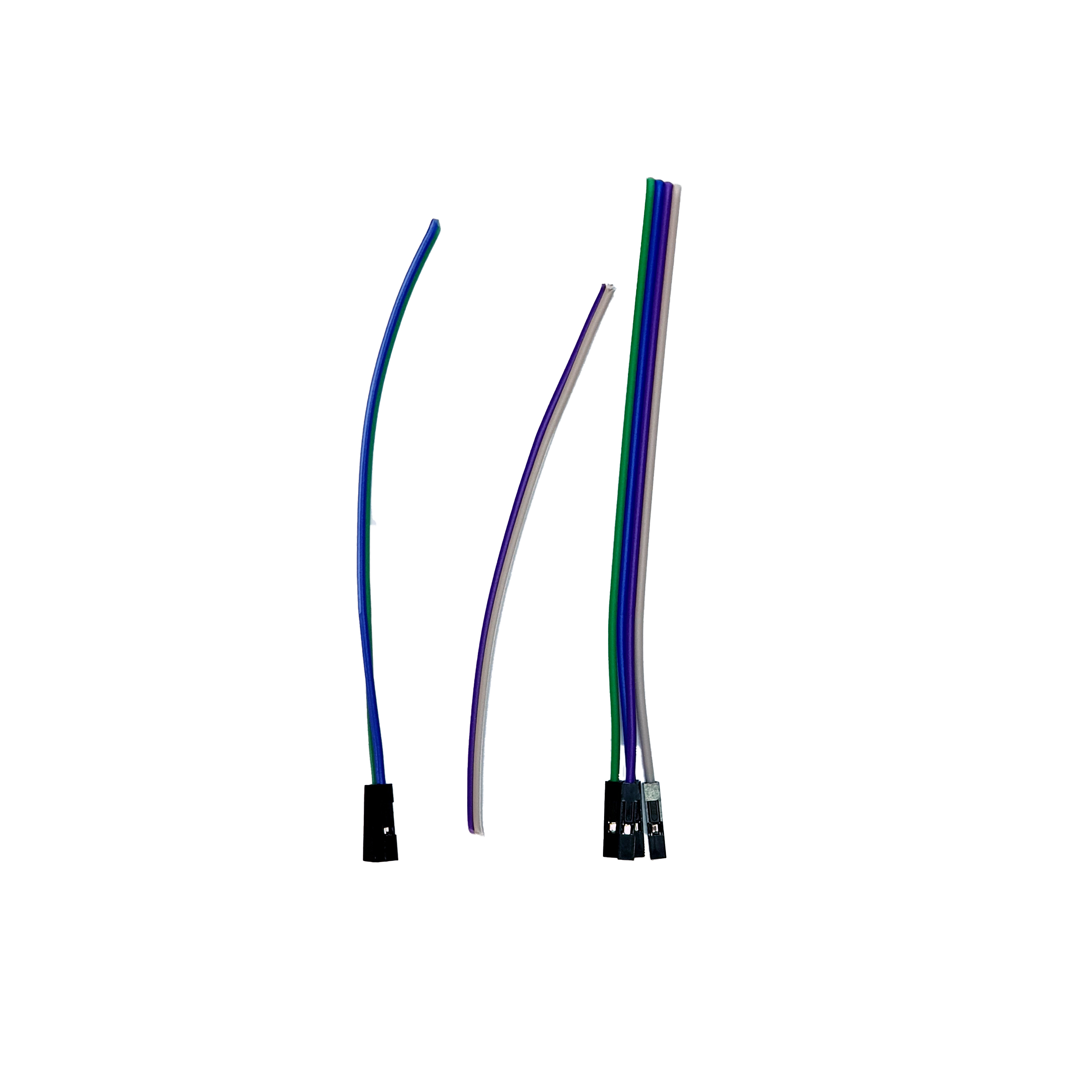
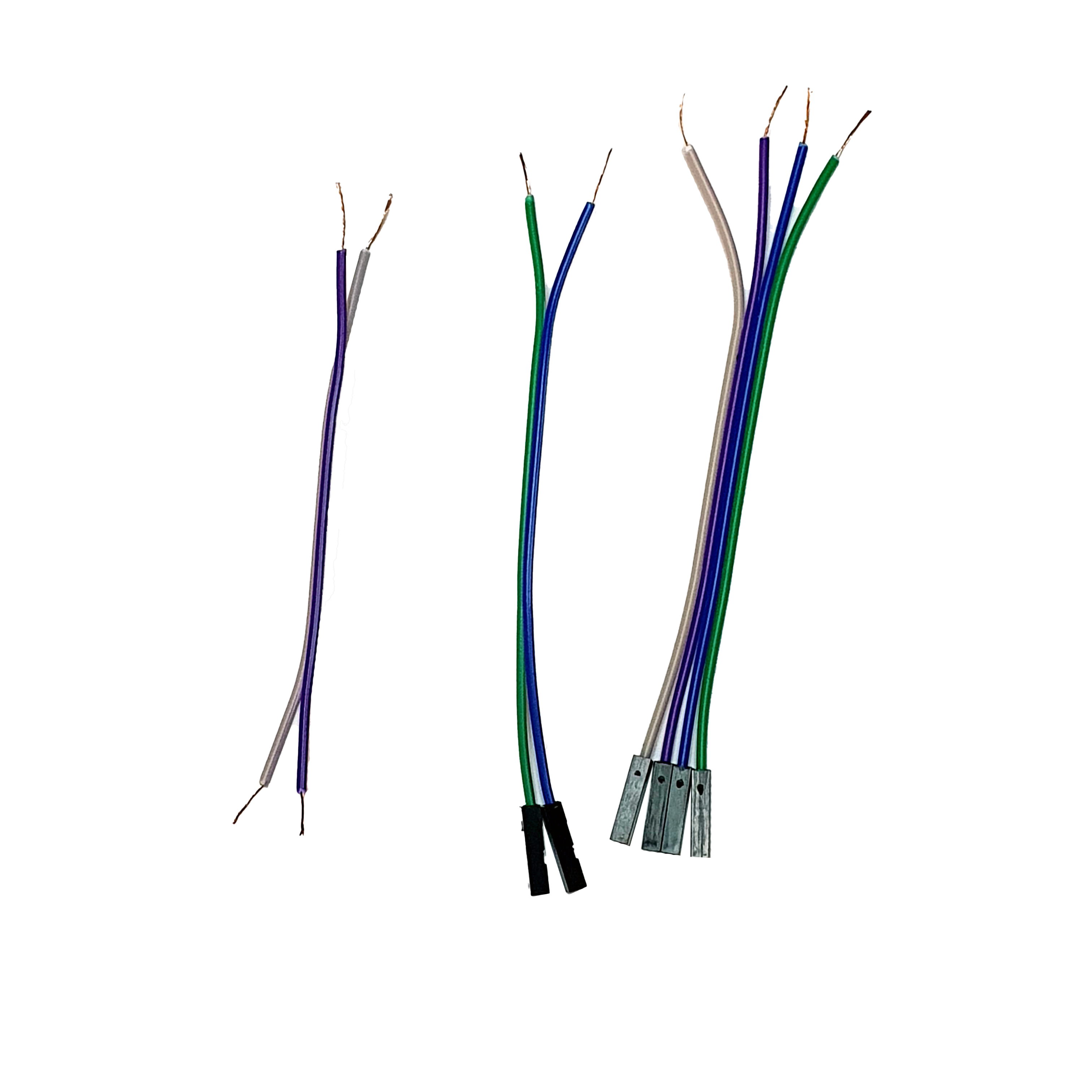
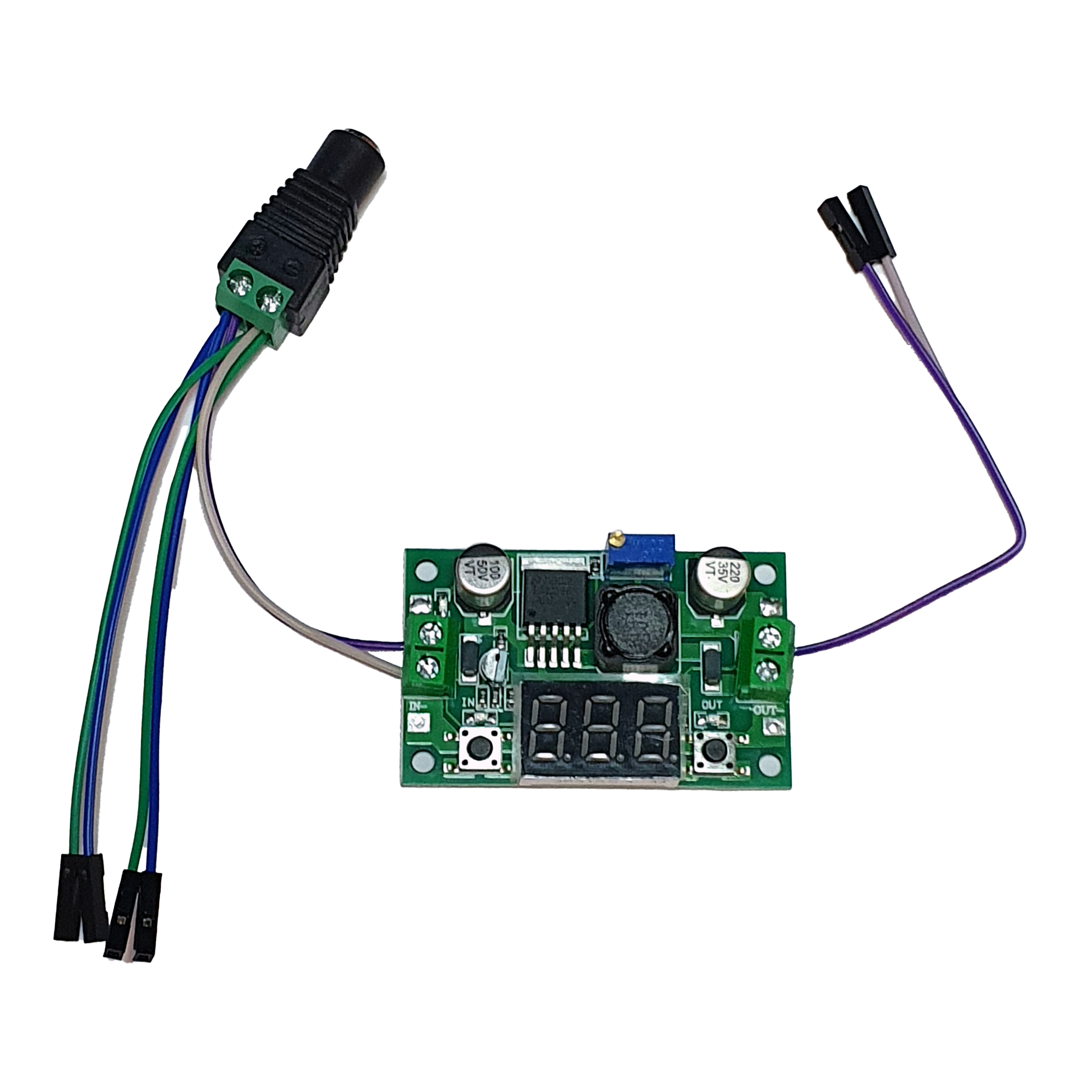
- Take 4 20 cm Female-Female Jumpers and cut them in half.
- Also, cut the Dupont female end of 1 pair.
- Strip the ends of all wires.

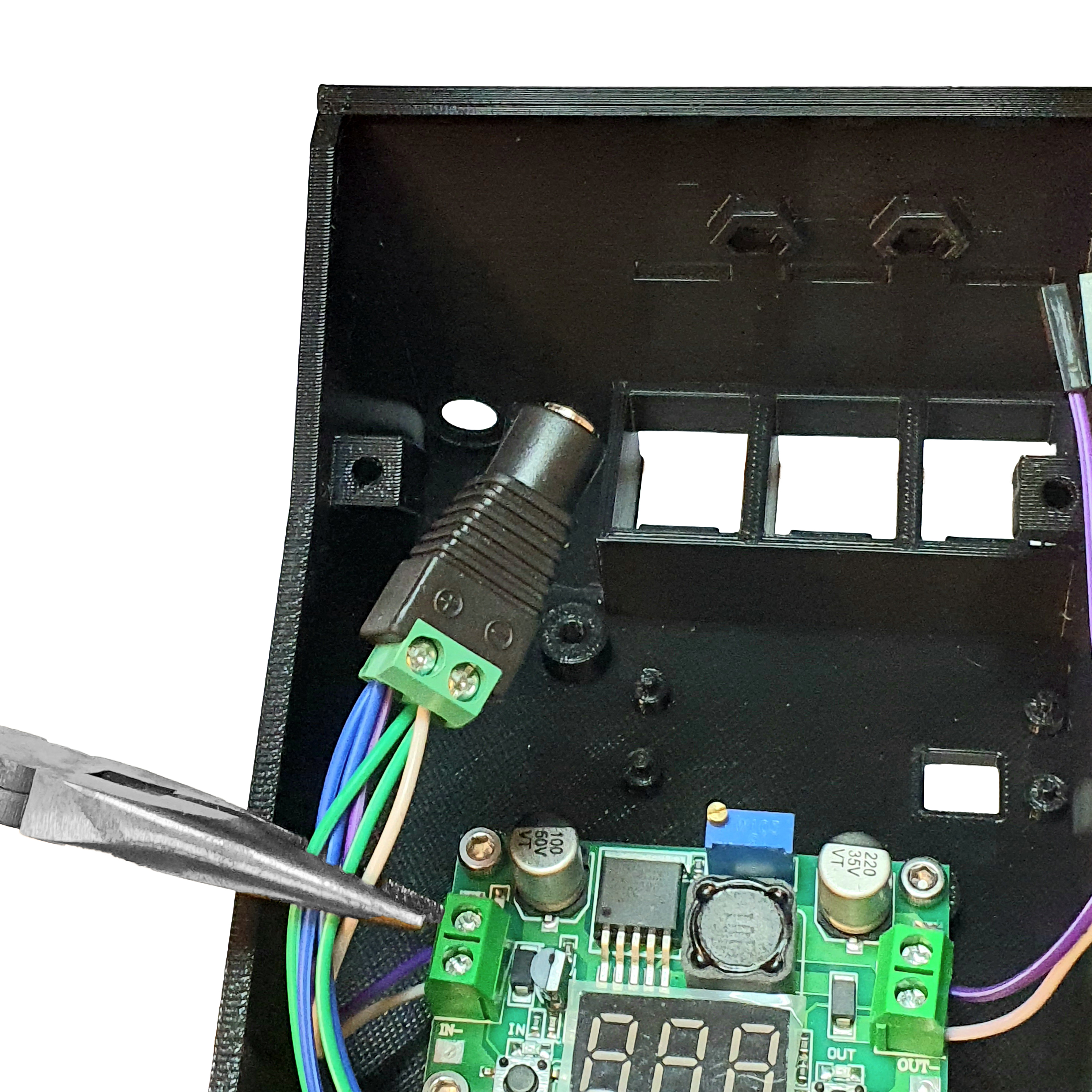
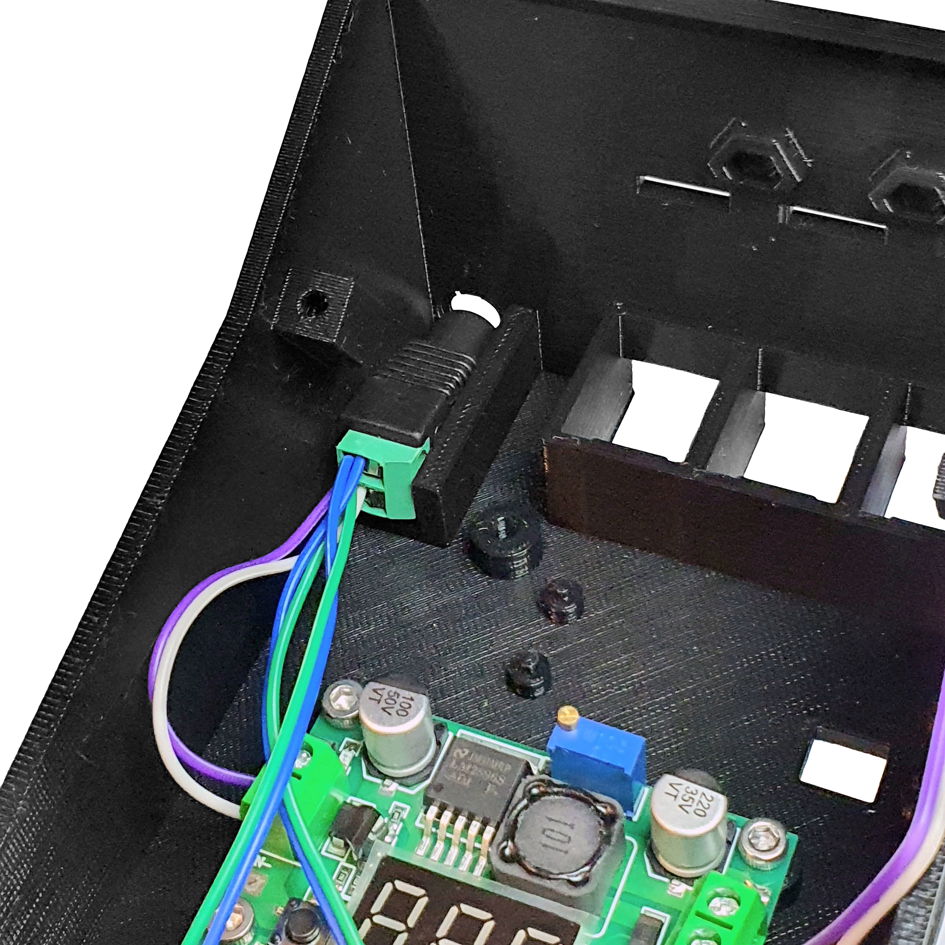
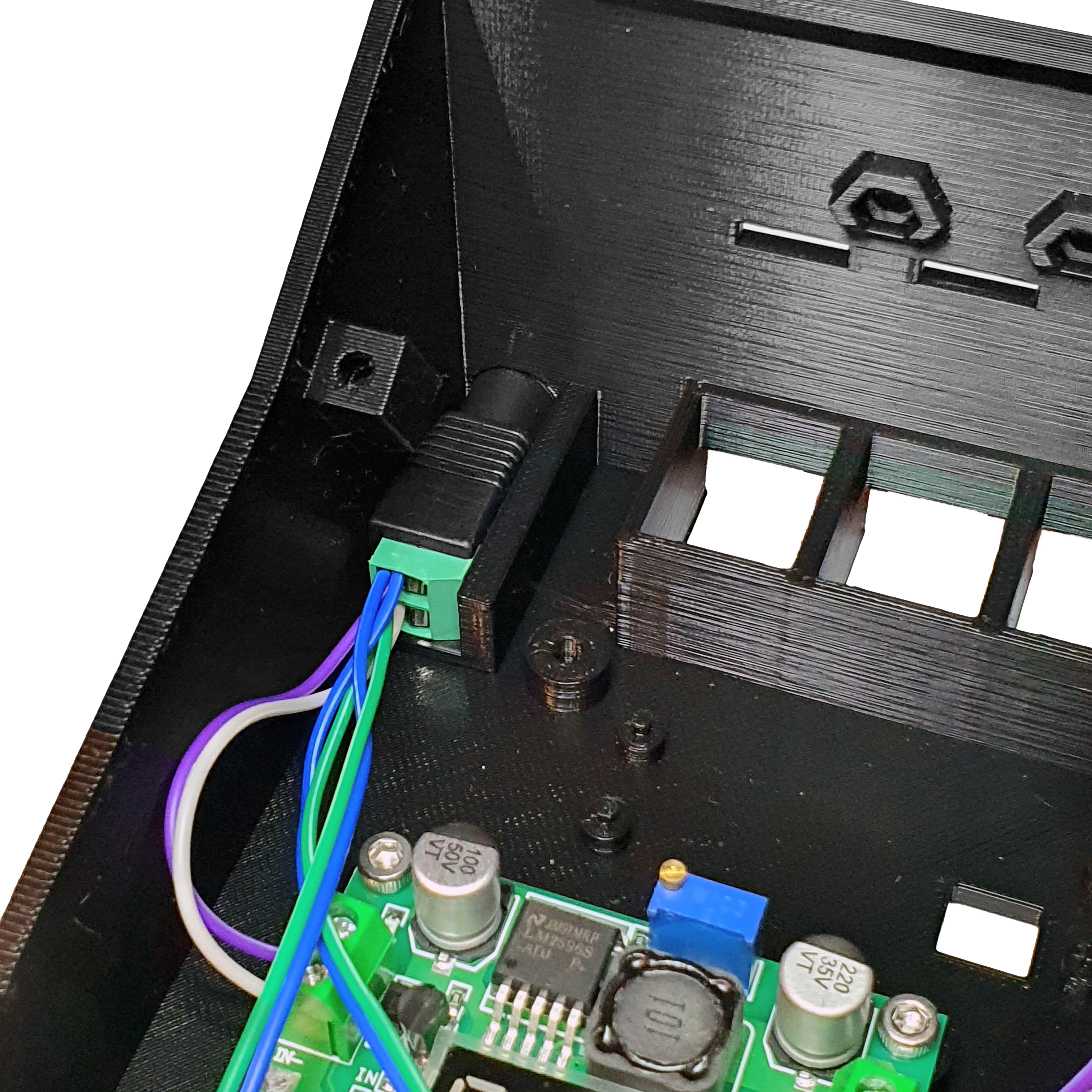
- Take the voltage regulator and the 5.5mm female jack connector.
- Connect them according to the wiring diagram.

Step 2: Fix the Voltage Regulator PCB on the Base
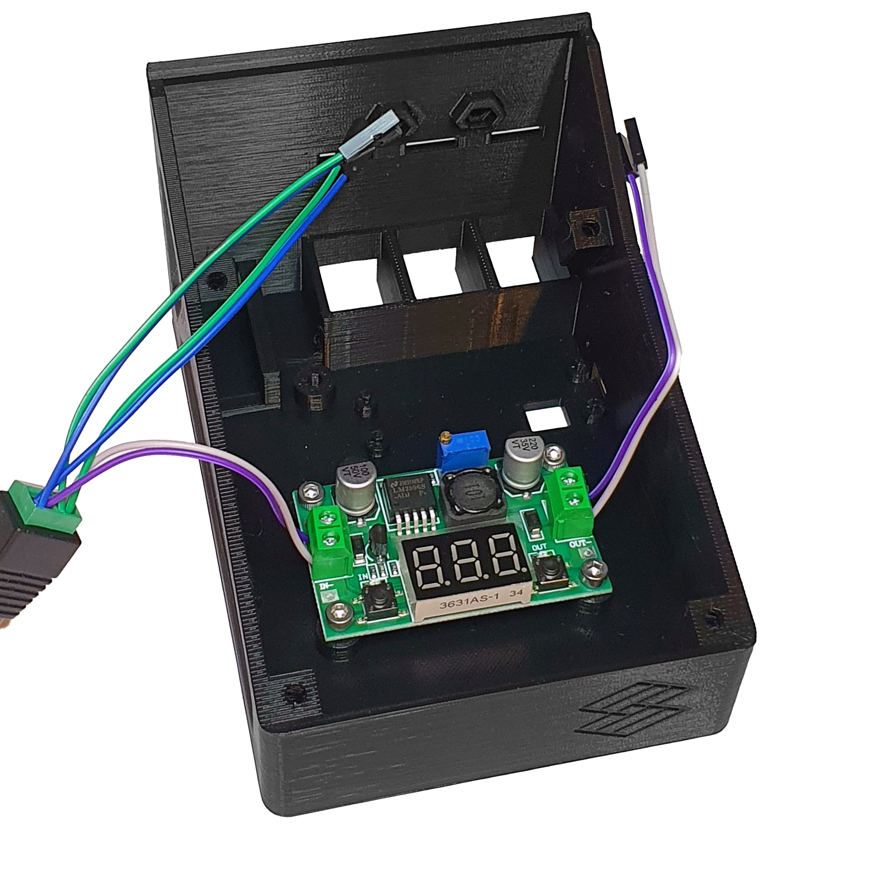
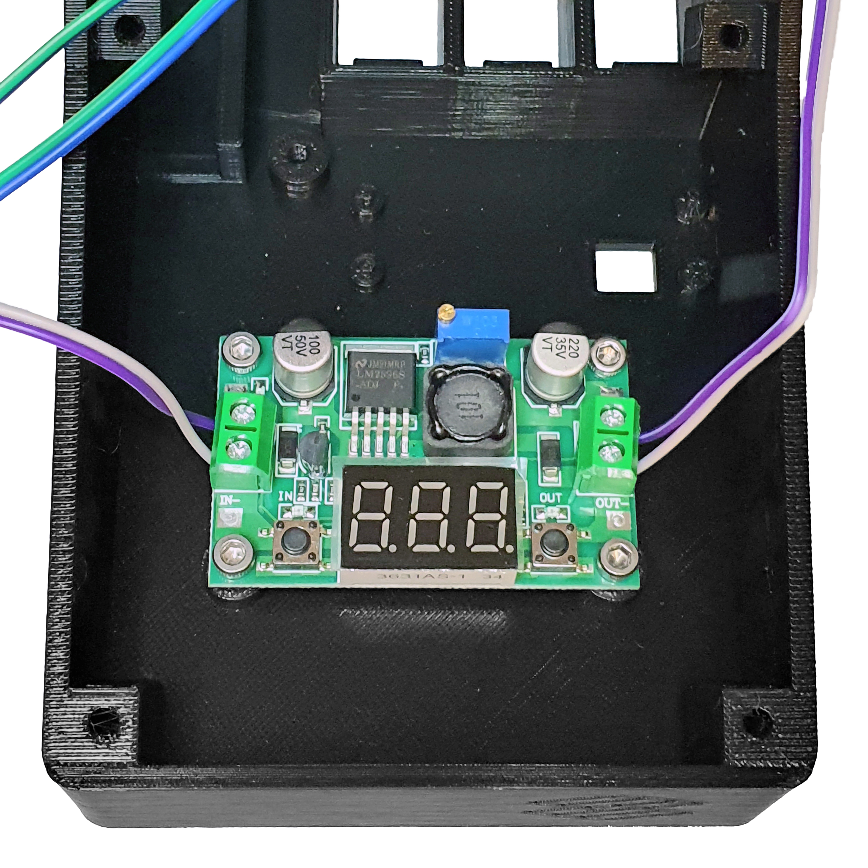
- Use 4 M3 10mm screws and M3 nut to secure the already wired voltage regulator.
- Attach it to the interface base, making sure to place the M3 nut on the back side.

Step 3: Install the 5.5mm Female Jack Connector
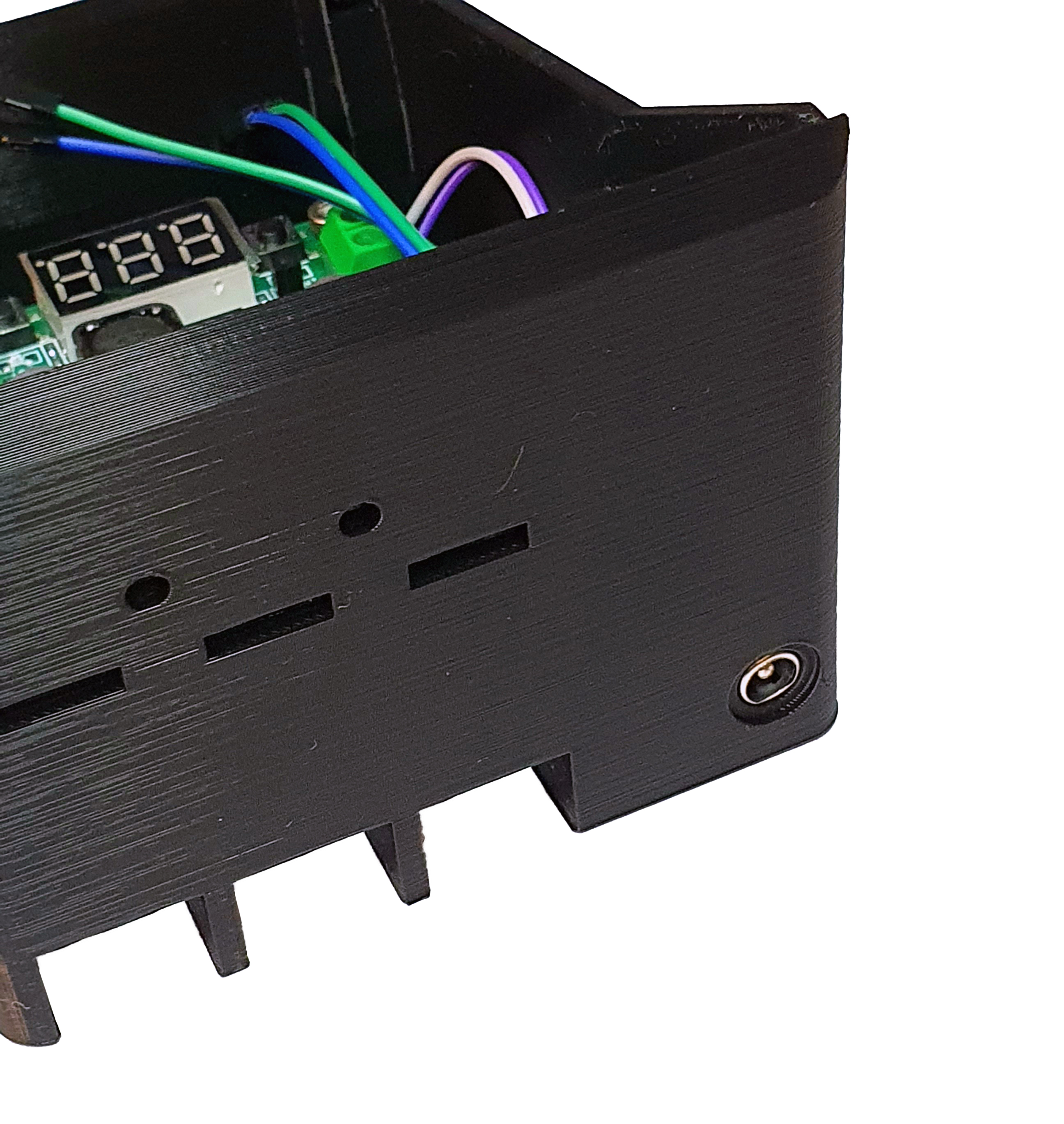
- With the voltage regulator in place, position the 5.5mm female jack connector in the top left corner of the base.
- Apply moderate force to ensure a tight fit.

Step 4: Install the Raspberry Pi Pico
- Take the 40 pin header and cut them in half.
- Solder them onto the Raspberry Pi Pico
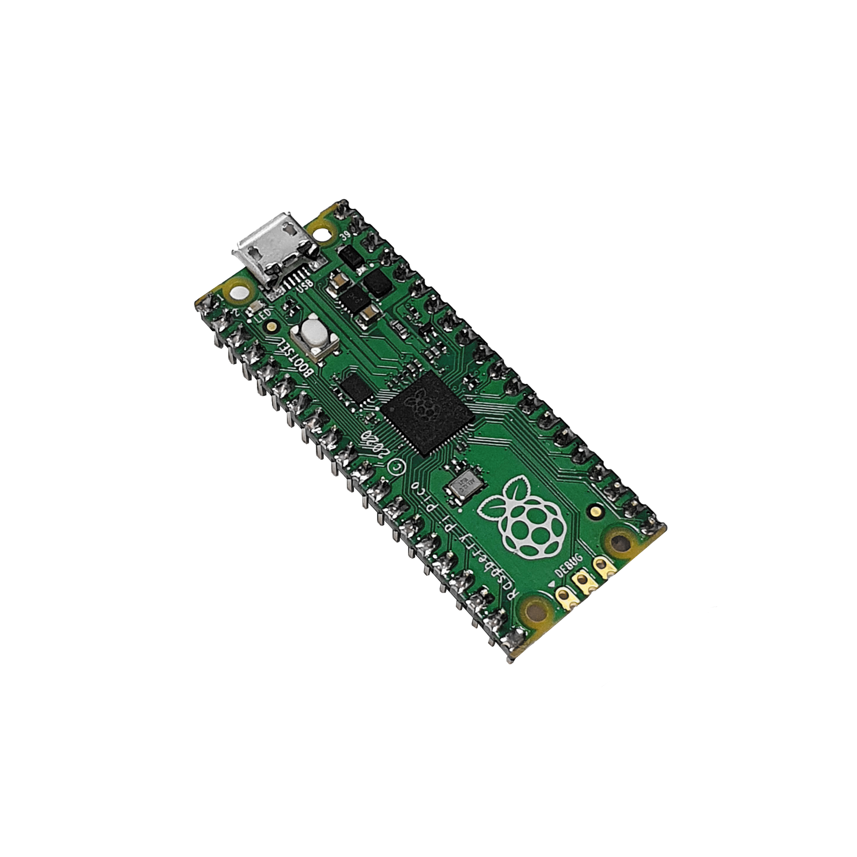
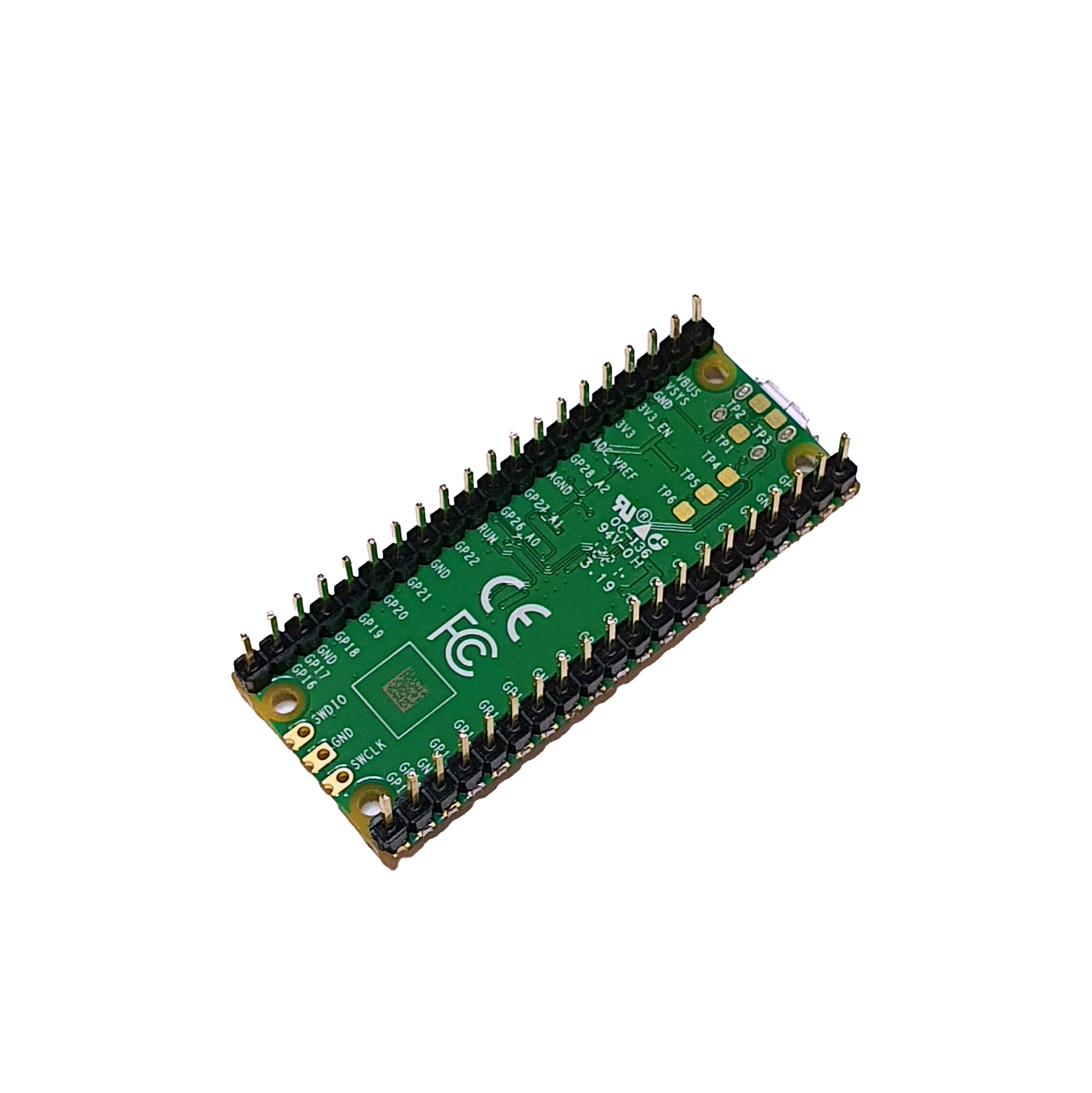

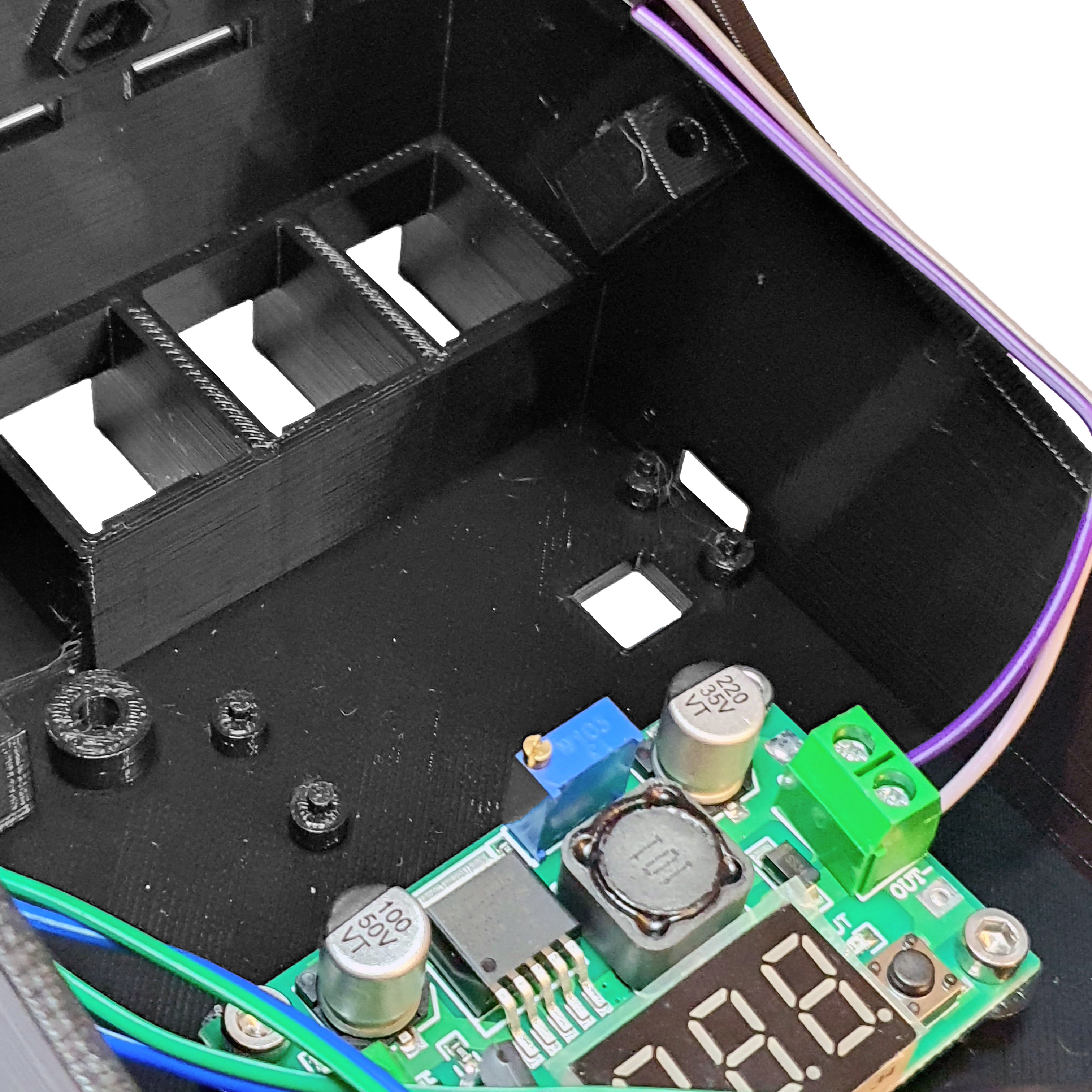
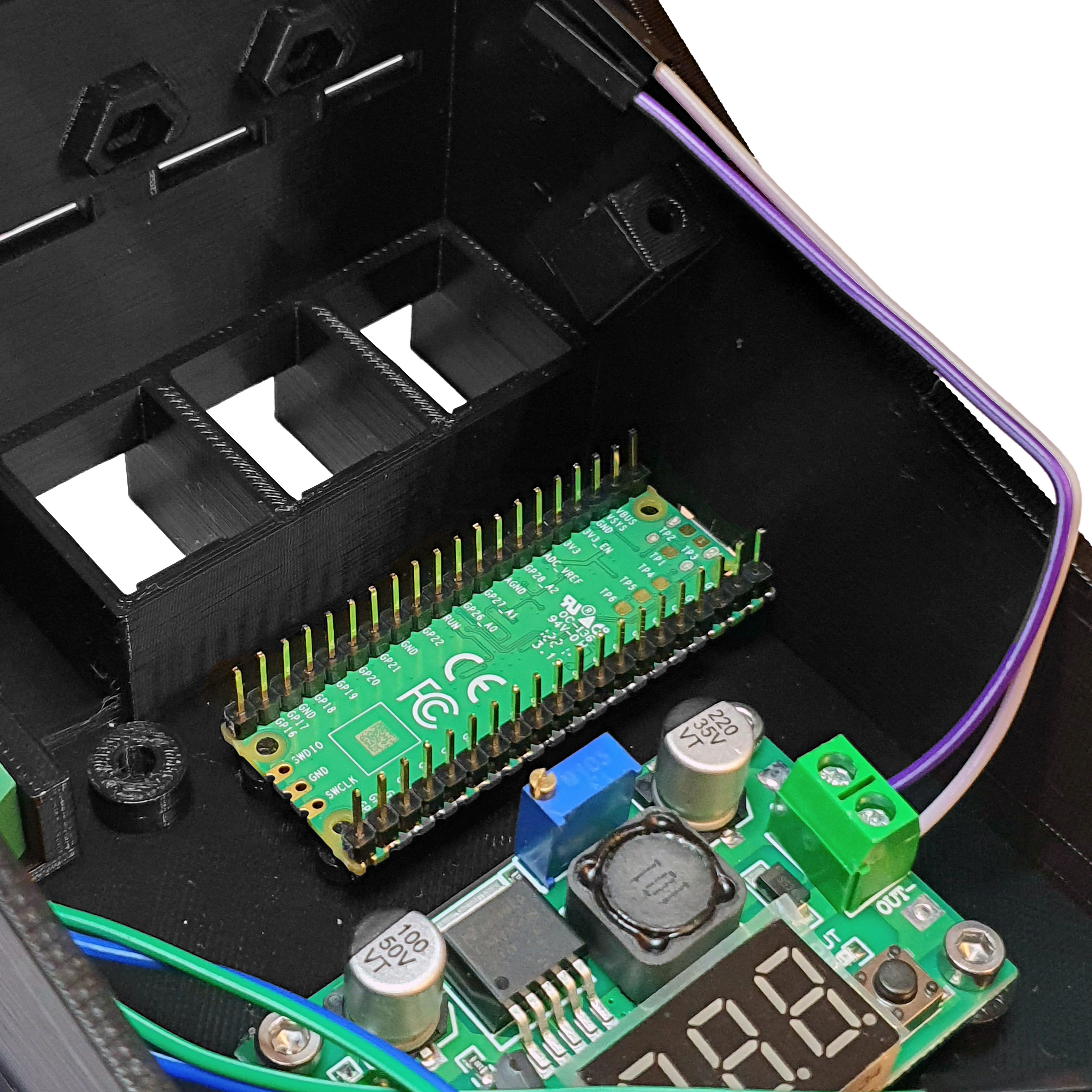
- Place the Raspberry Pi Pico upside down, aligning the holes with the pins on the base.
- Ensure that the USB port aligns with the respective hole.
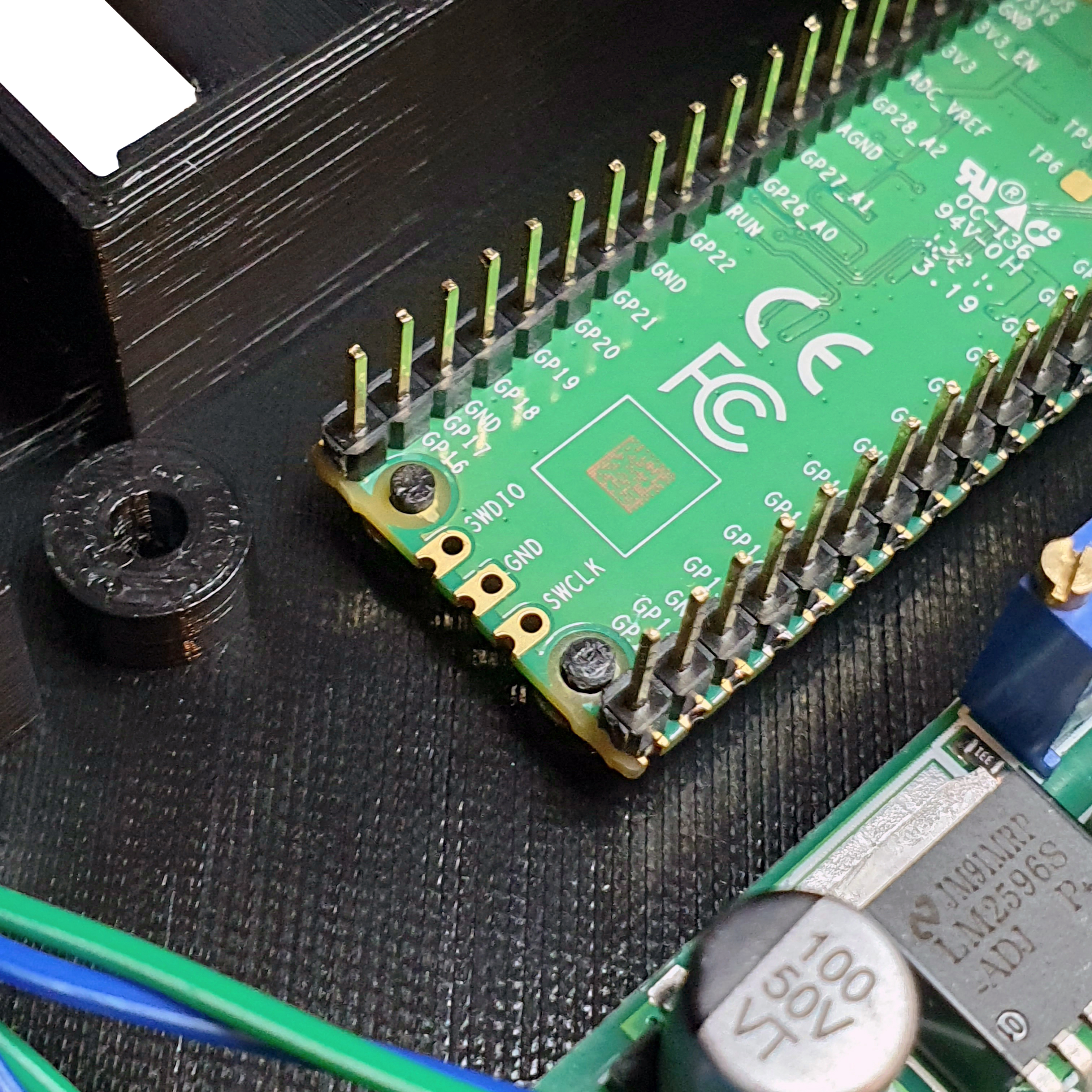
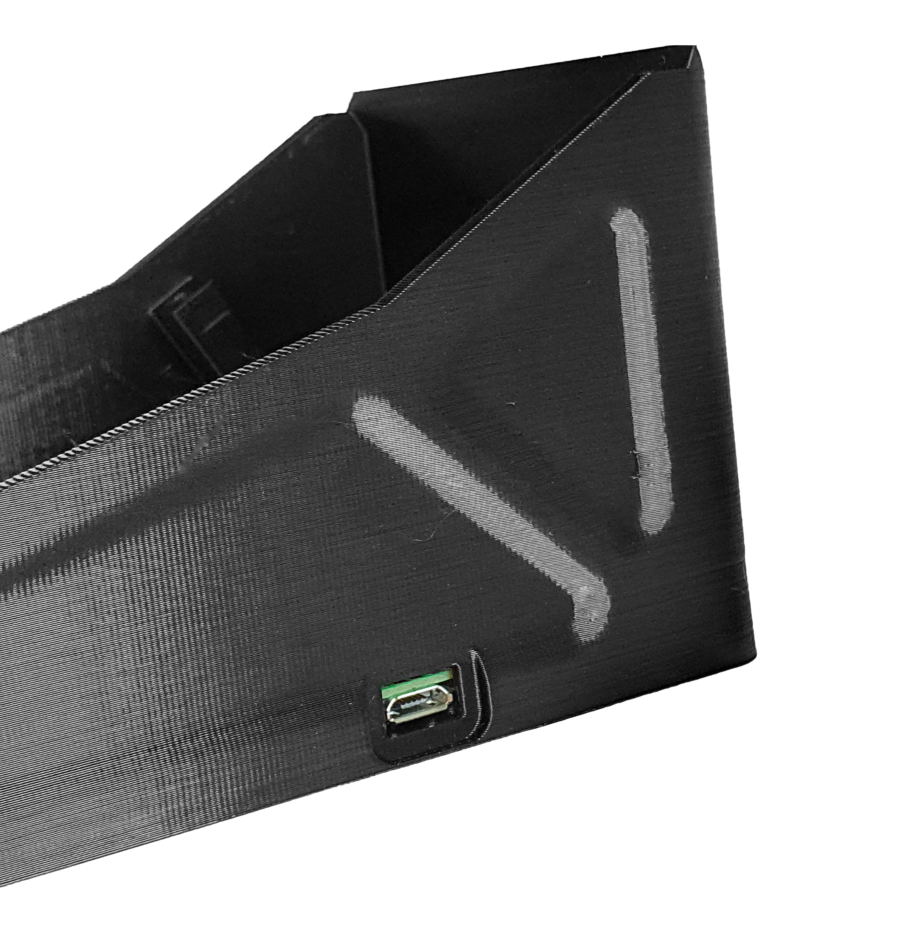

Step 5: Wiring the Pico and Voltage Circuit
- Take the two cables that come out of the voltage regulator.
- Connect the positive cable to the 40th pin of the Raspberry Pi Pico.
- Connect the negative cable to the 3rd pin of the Raspberry Pi Pico.
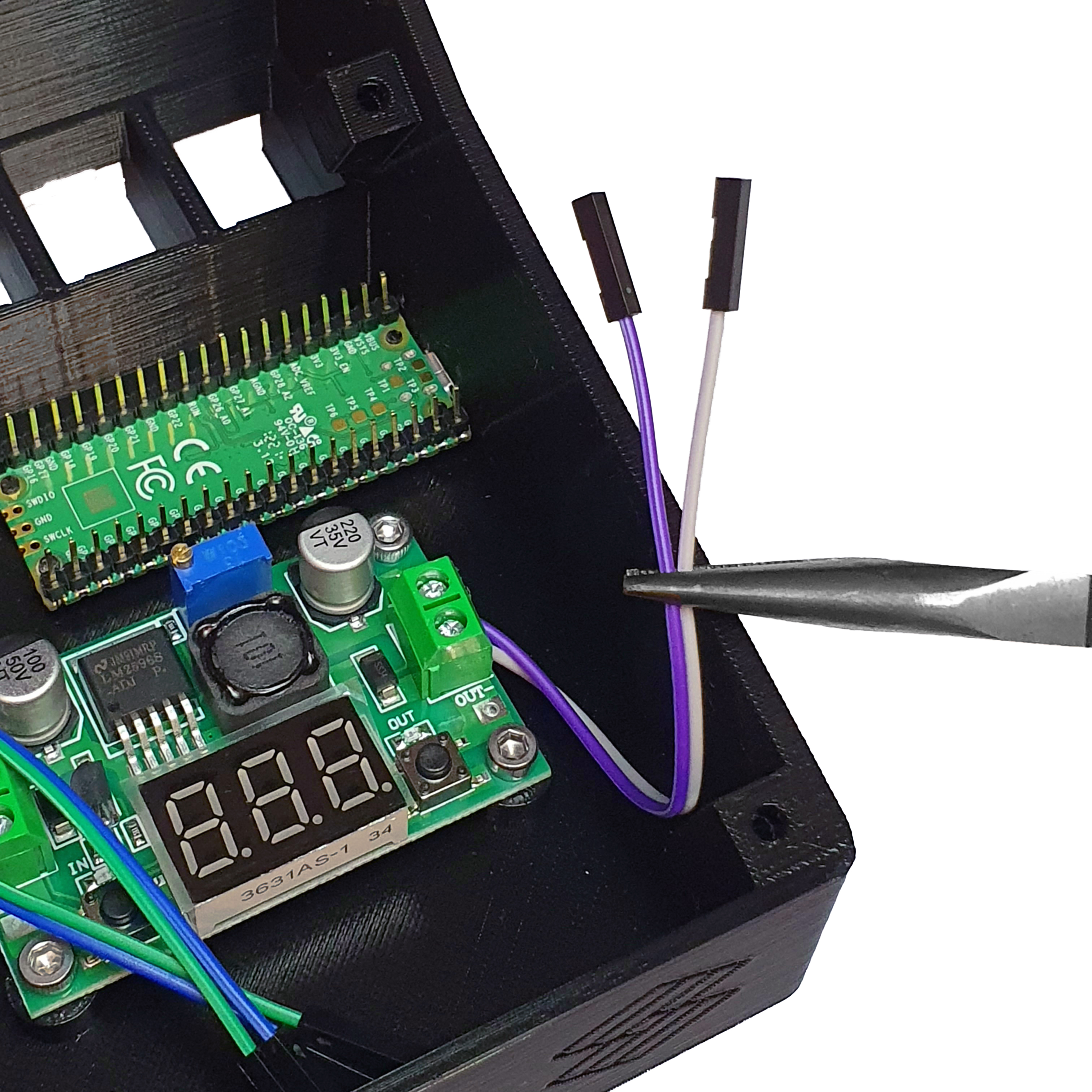
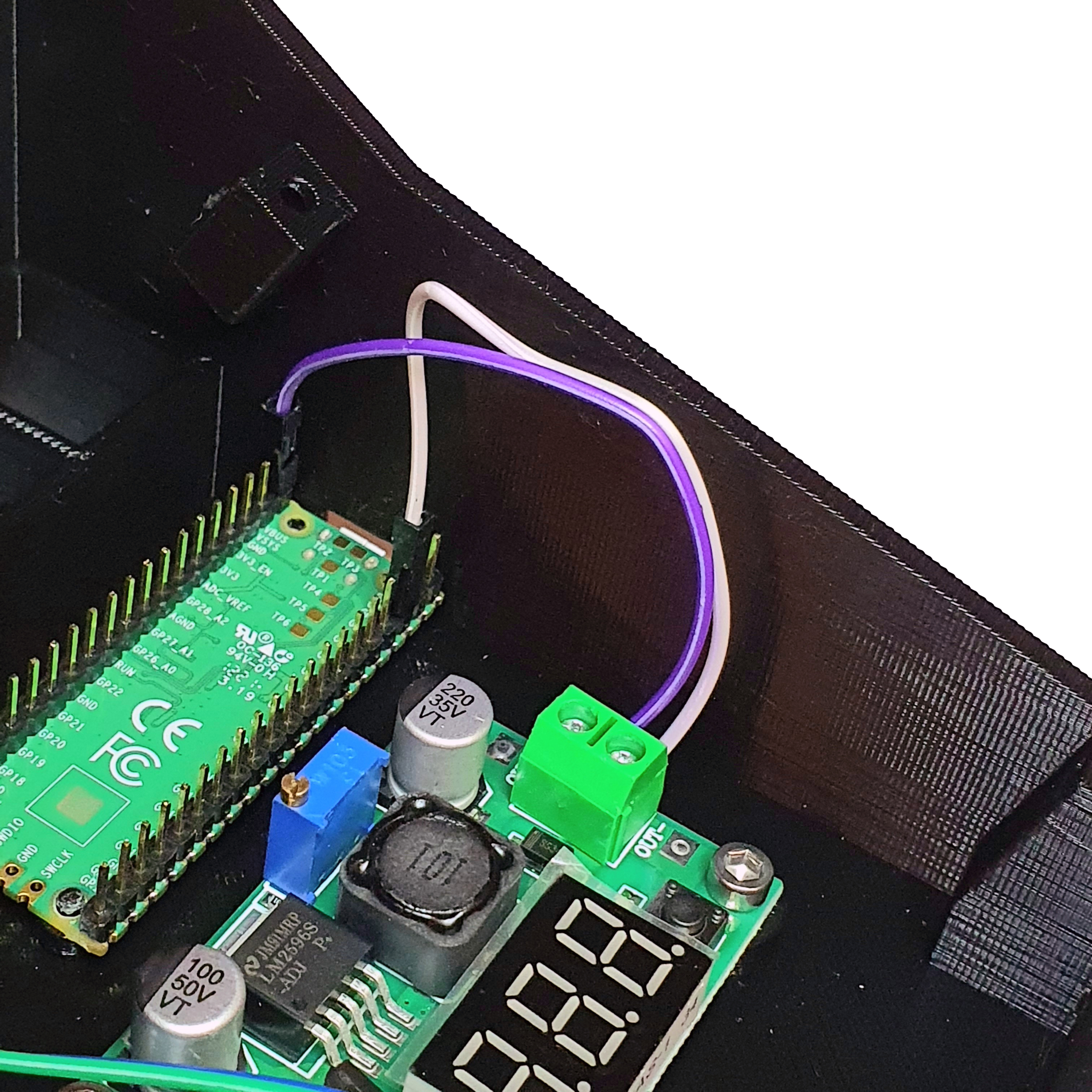

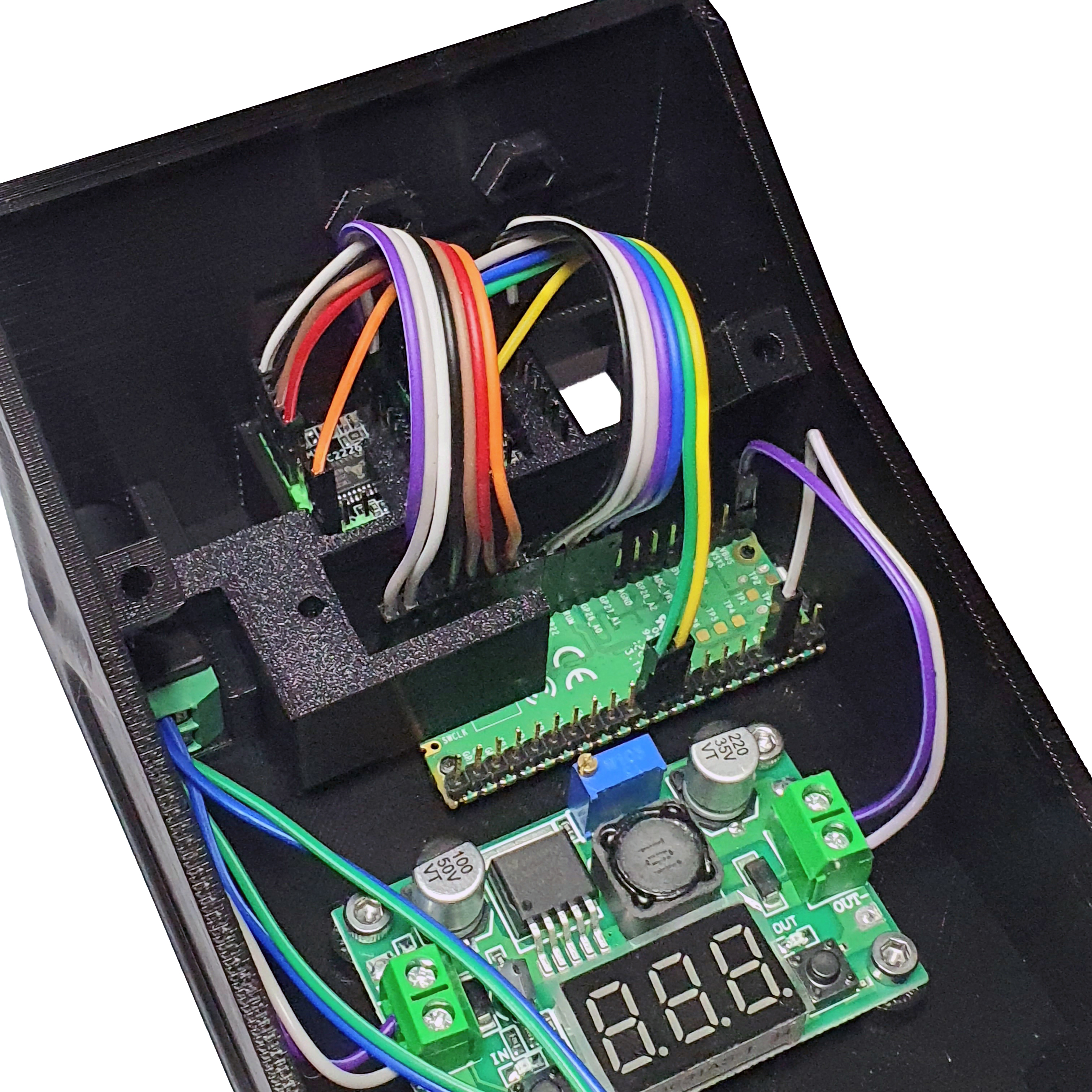
Step 6: Install the Motor Drivers
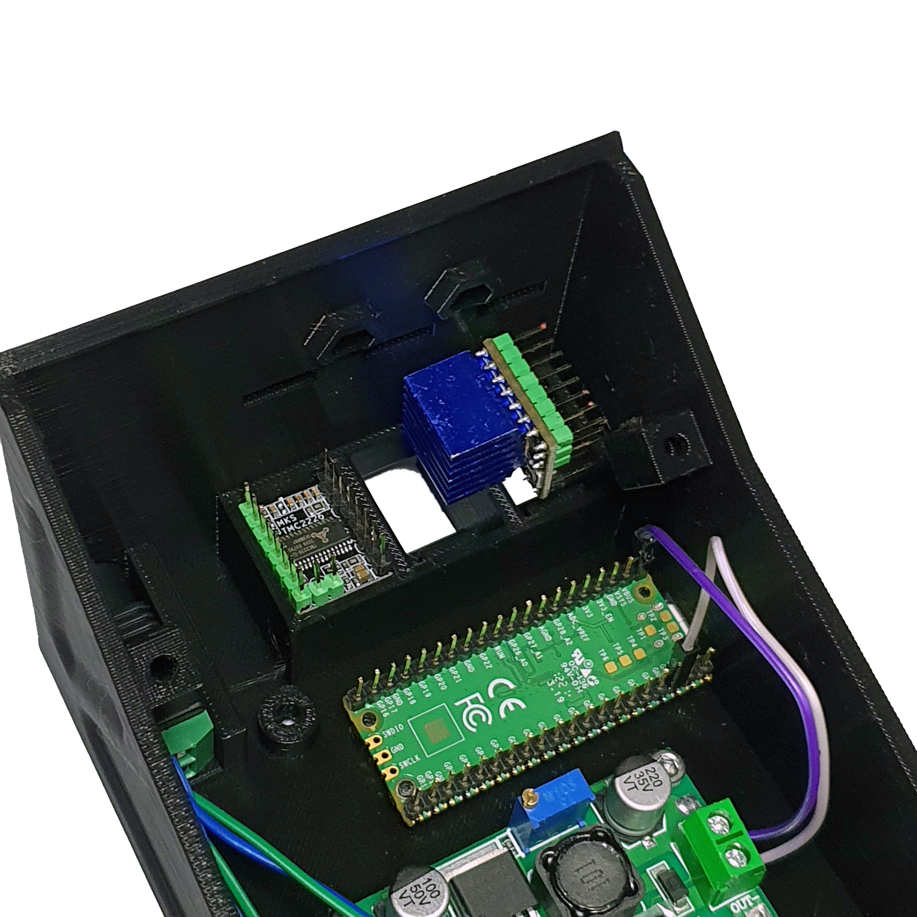
- Take 2 TMC2209 driver and attach the heatsinks.
- Make sure to attach them in the positions shown below.
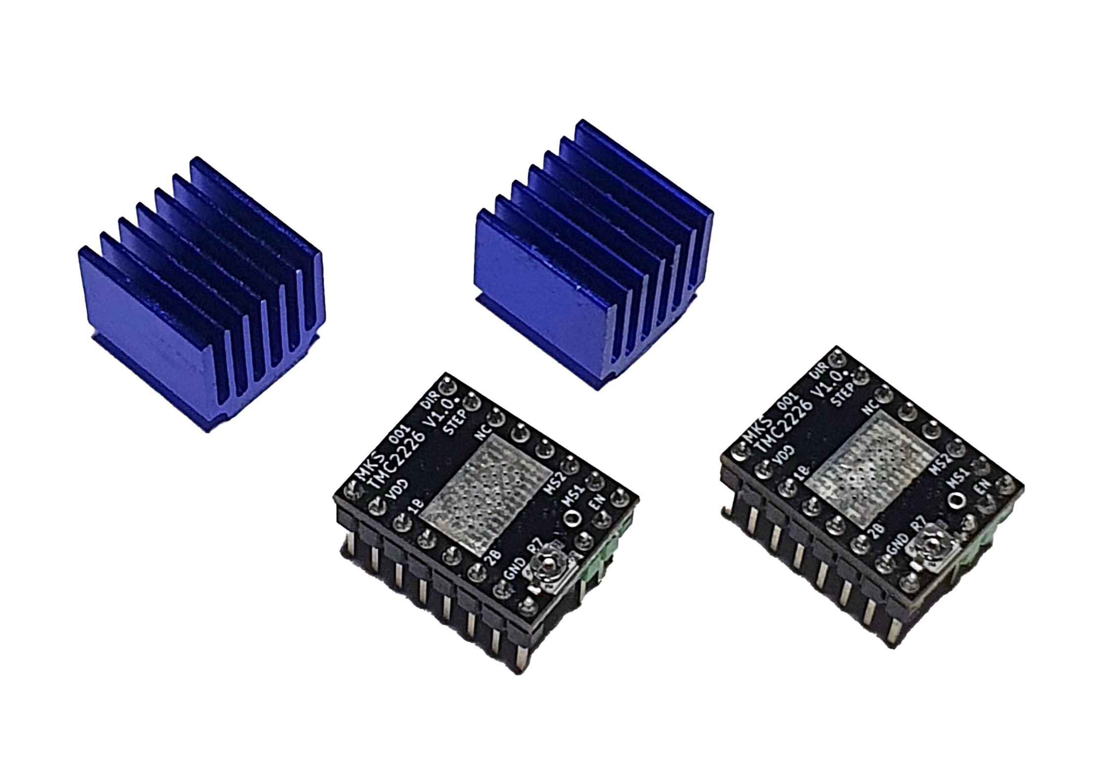
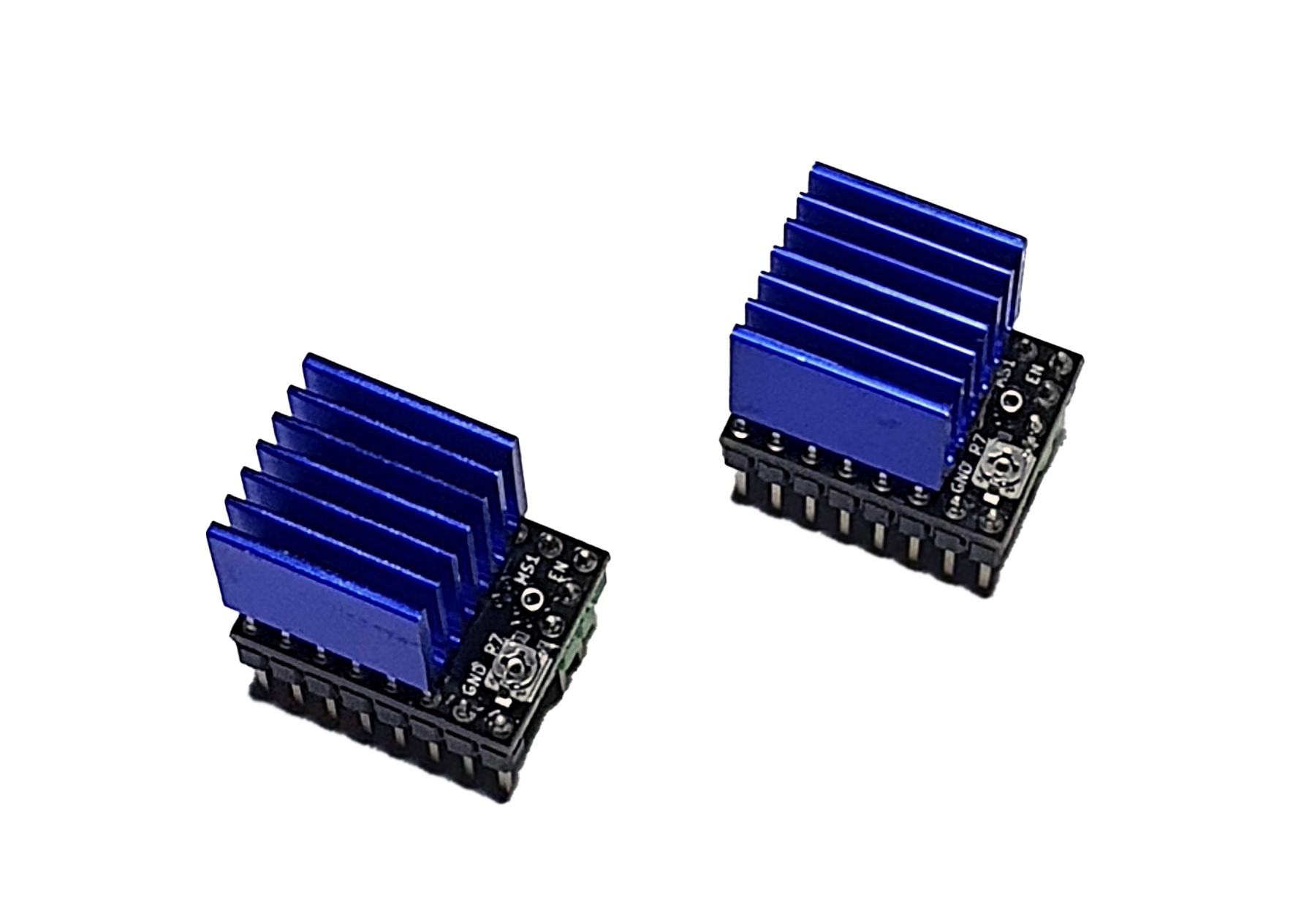

- Take 7 10 cm female-female jumper and connect them to the following pins of the TMC2209 Driver.
- Repeat the process for the other TMC2209 Driver motor driver.
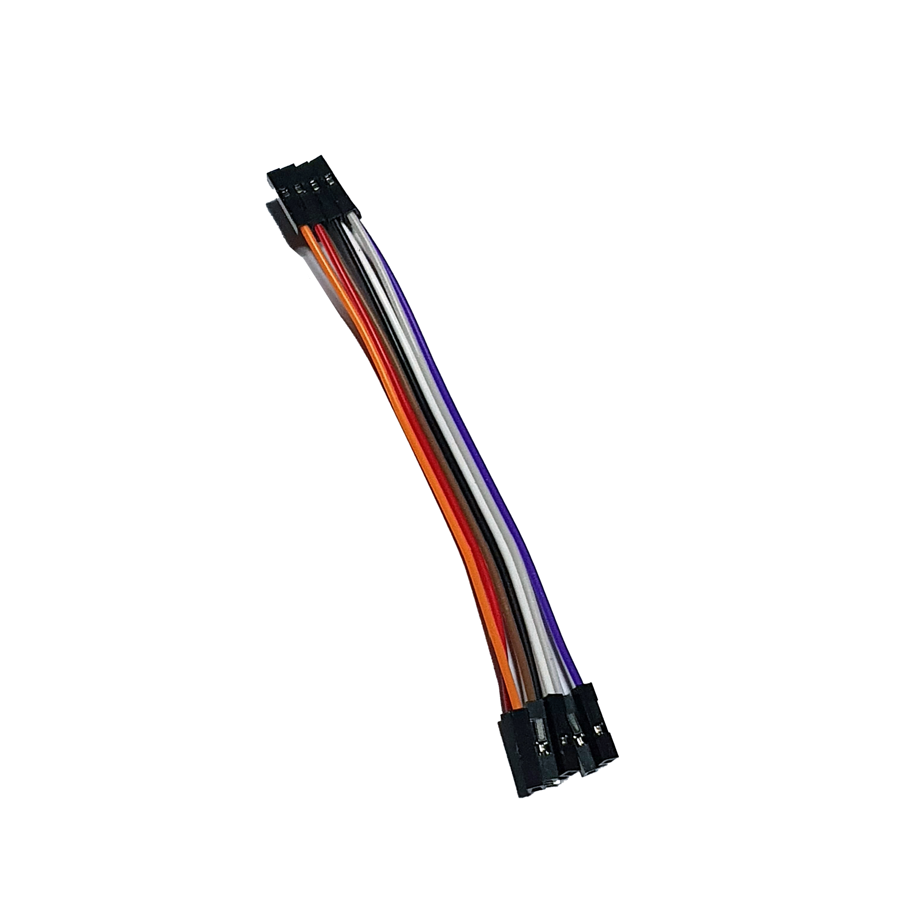
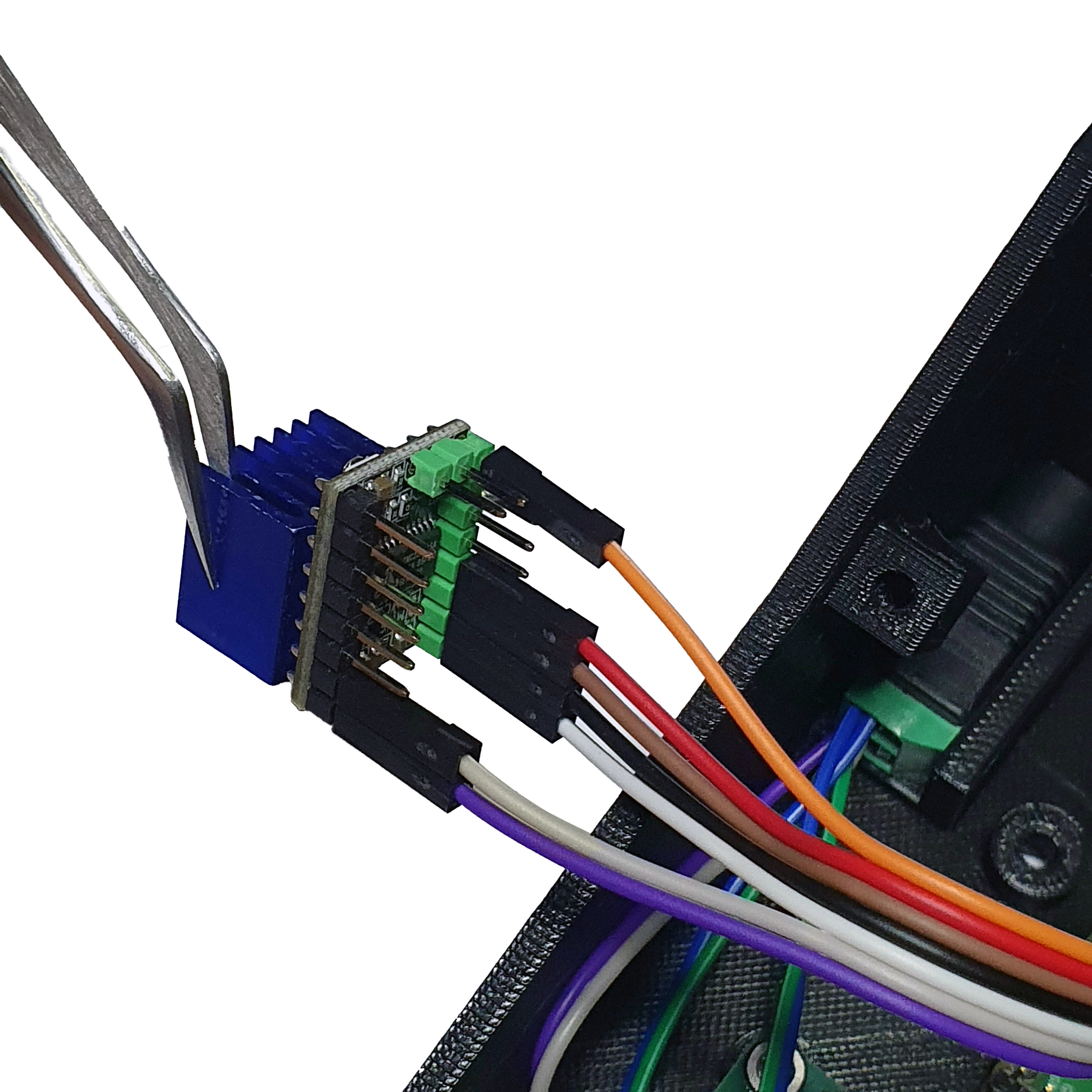
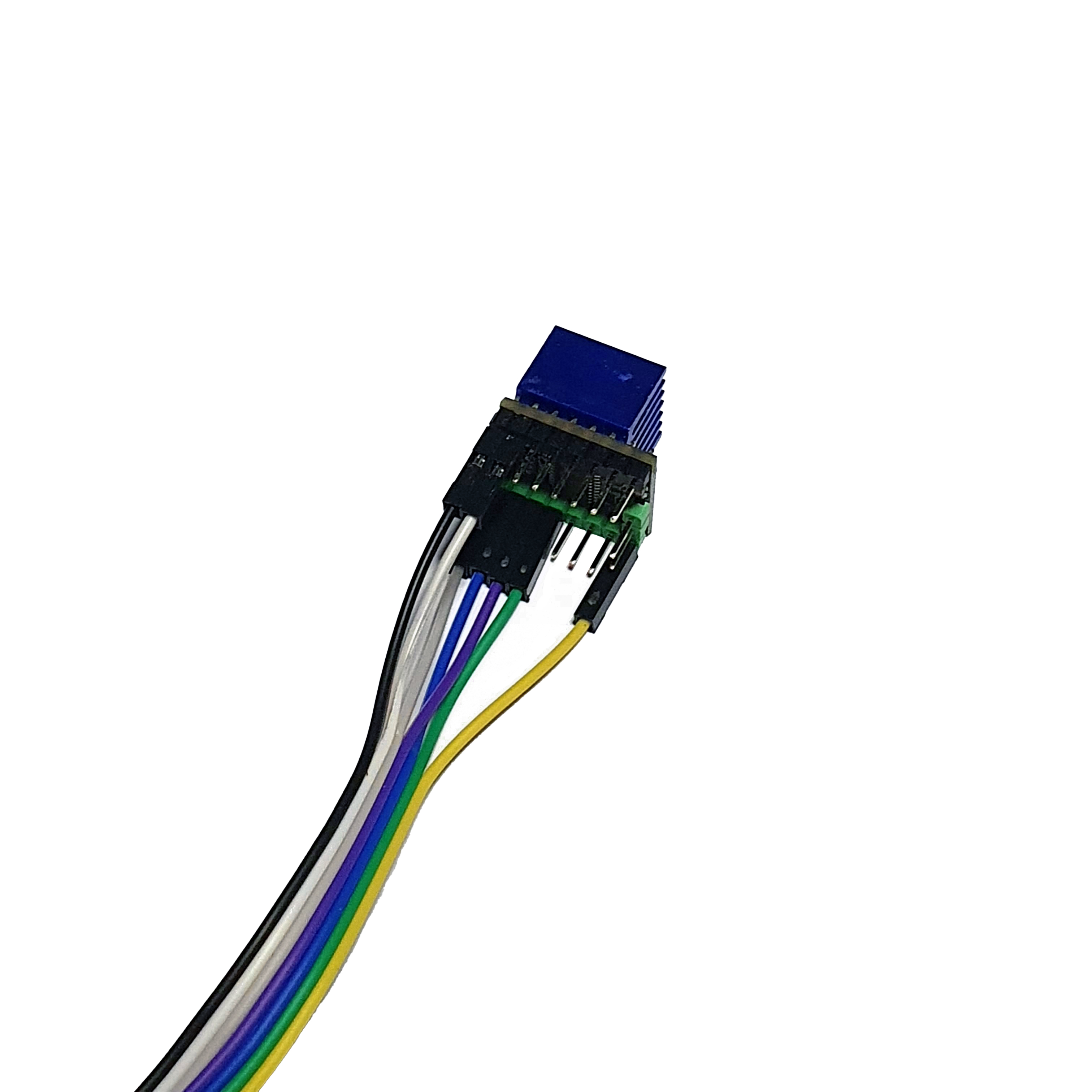

- Connect the two TMC2209 Driver to the Raspberry Pi Pico pins.
- Follow the diagram and the images below.
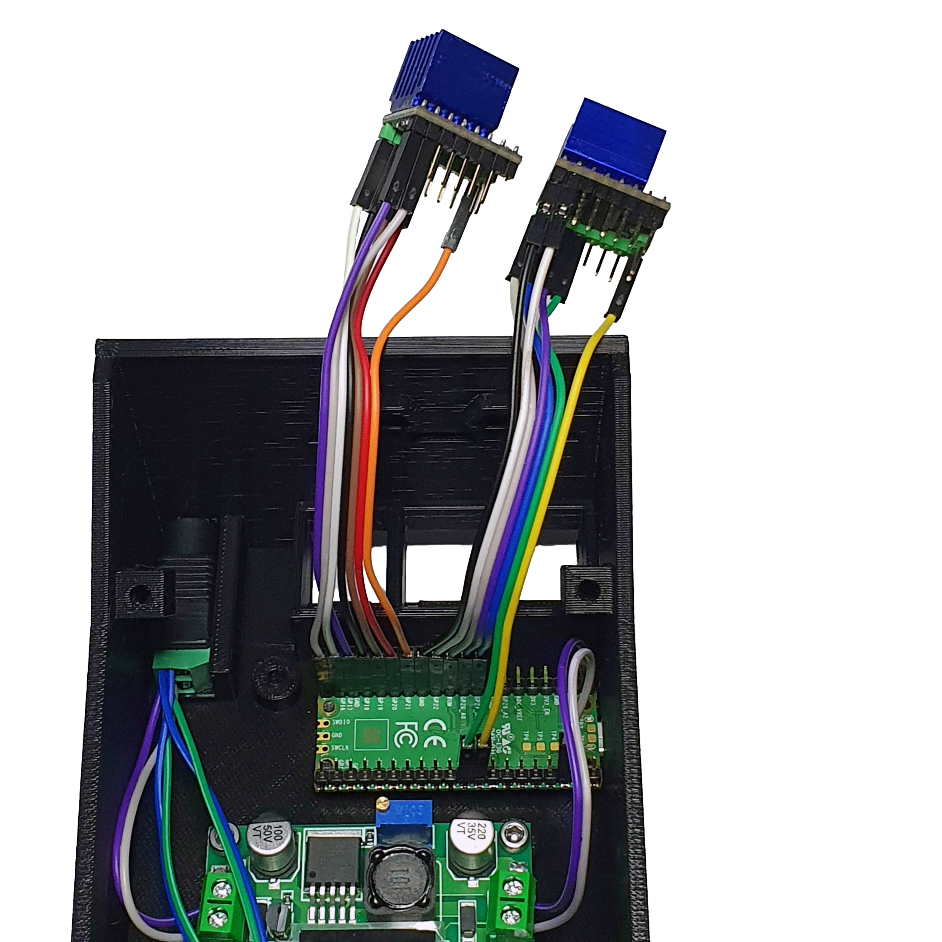

- Insert the TMC2209 Driver into the corresponding holes.

Step 7: Fix the Electronics Holder
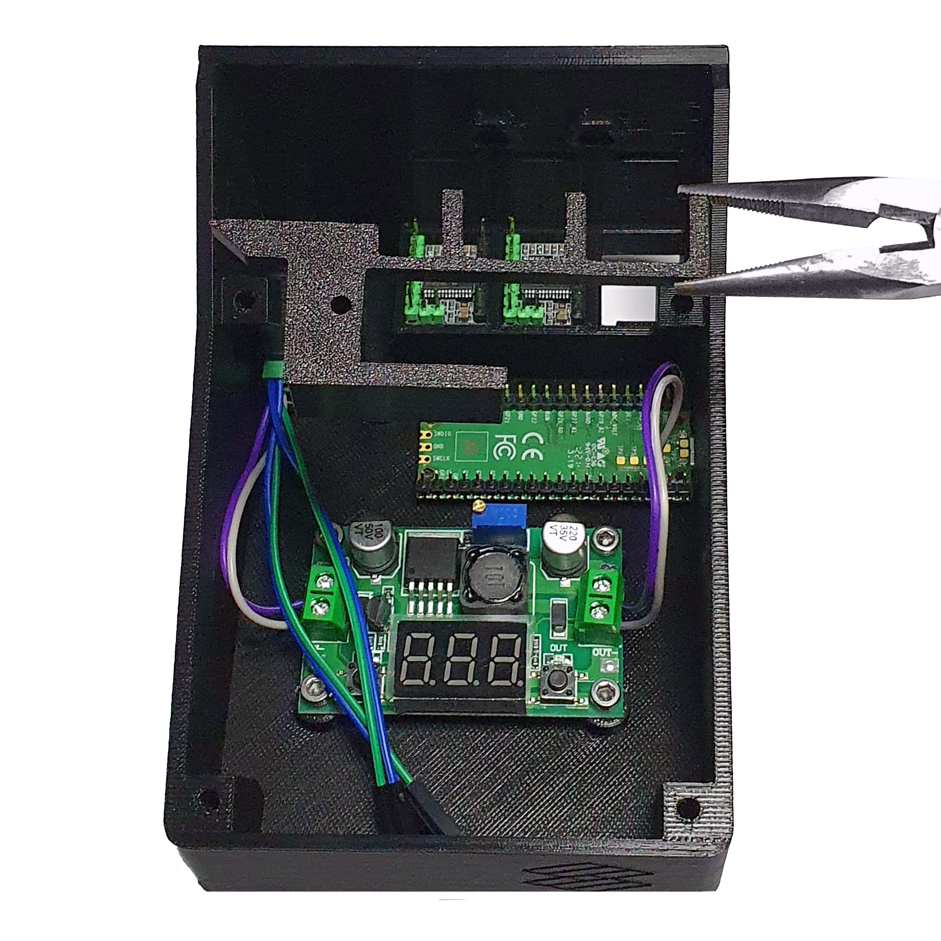
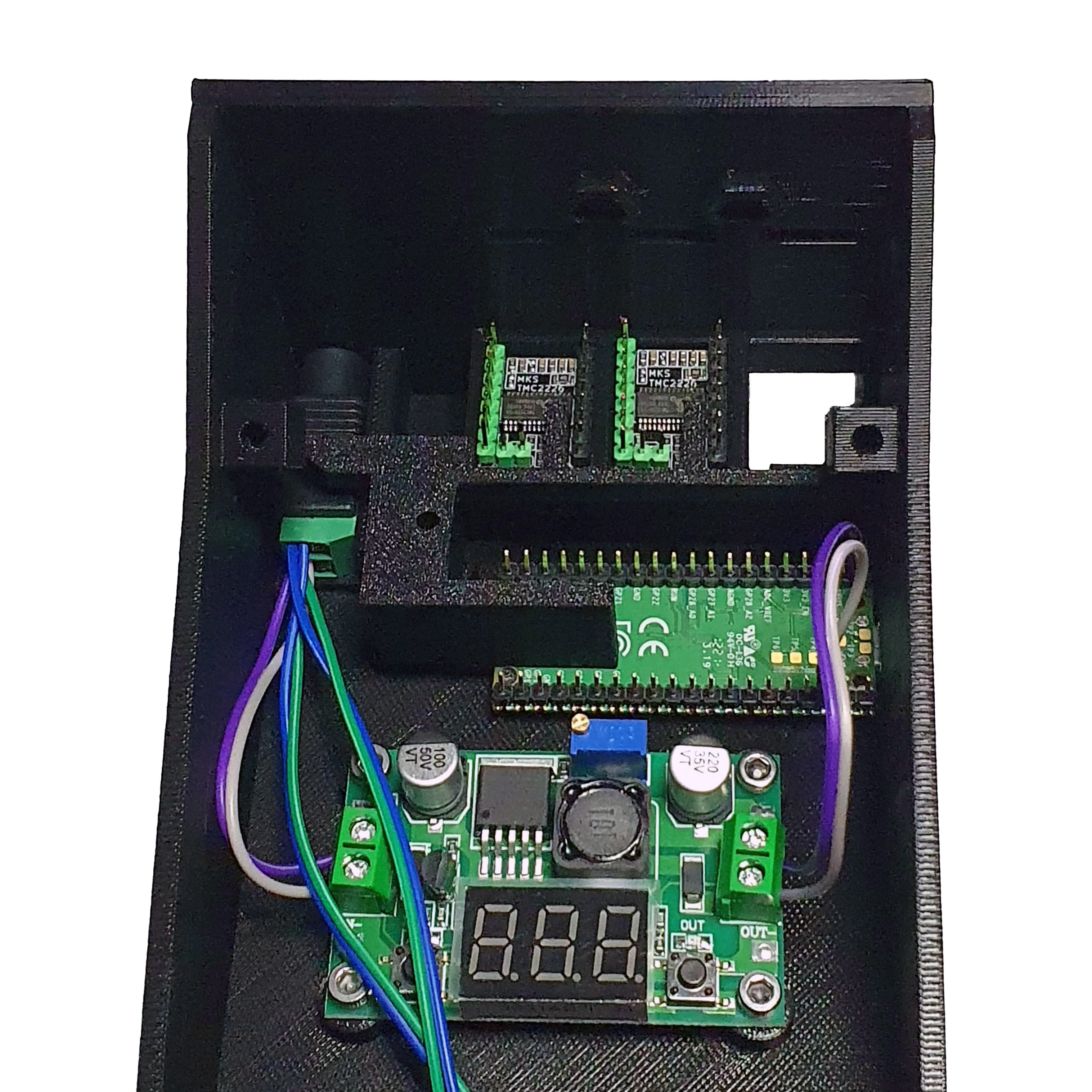
- Take 1 M3 25mm screw and M3 nut.
- Use them to secure the electronics holder in place.
- The electronics holder should keep the electronic components securely in place.

Step 8: Rear Cables
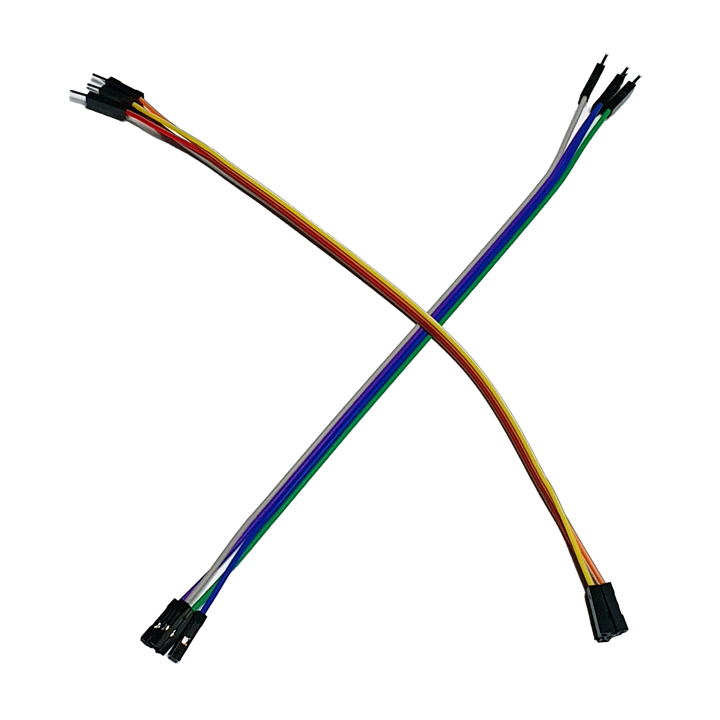
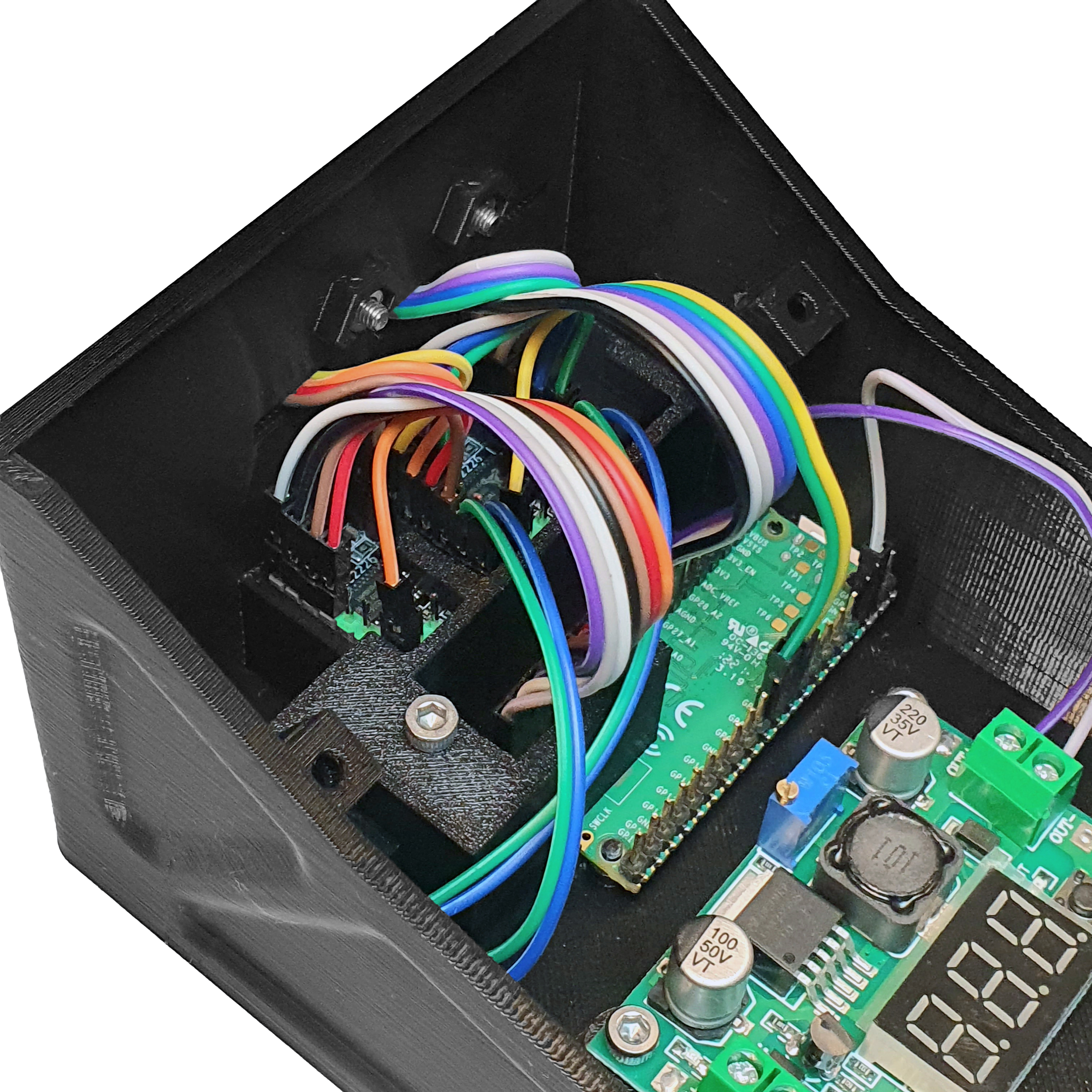
- Take 4 20 cm female-female jumpers and connect them to the 4 pins shown below on one of the TMC2209 Driver.
- Thread the 20 cm female-female jumpers through the holes.
- Repeat the process for the other TMC2209 Driver.

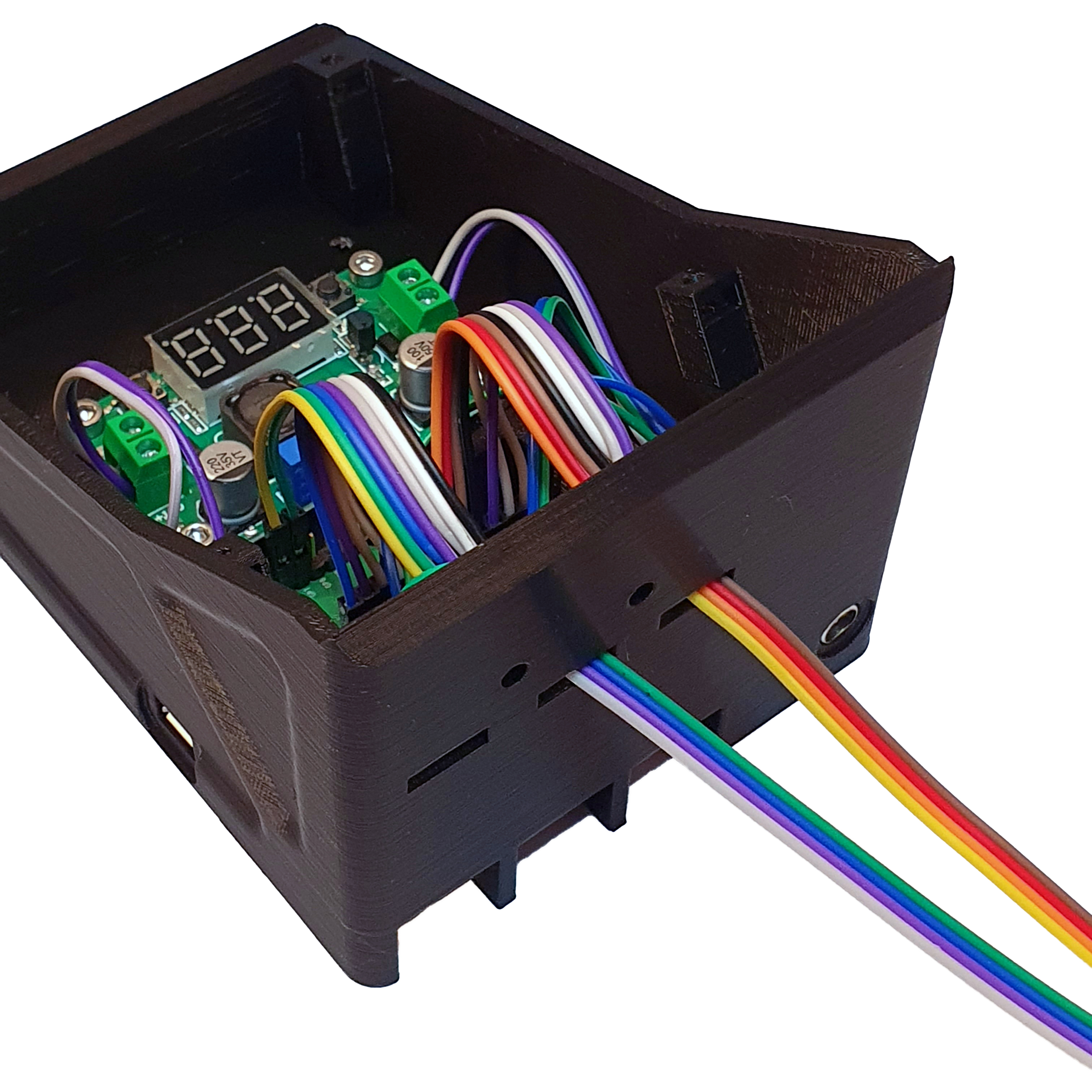

- Take 2 M3 10mm screws and 2 M3 nut.
- Secure the 20 cm female-female jumpers with the back cover.
- Ensure that the 20 cm female-female jumpers are arranged neatly. The lid should press firmly without cutting them.

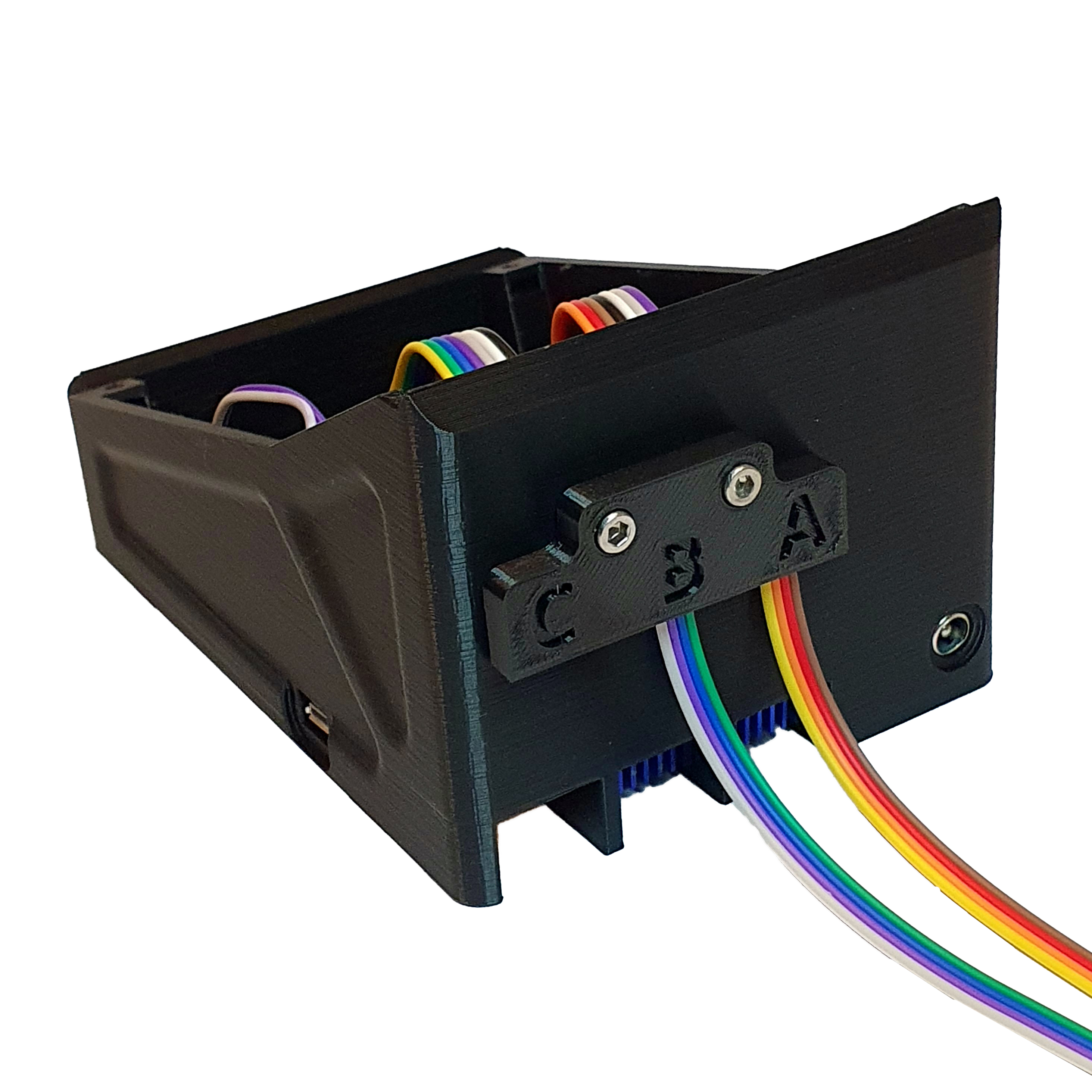

The Assembled Interface Base is now ready.