Assemble the illumination
Tools
- 1 #1 pozidrive screwdriver
- 1 2.5mm Ball-end Allen key
- 1 Crimper
- 1 Needle-nose plier
- 1 Precision wire cutter
- 1 Soldering iron
Consumables
Electronic Components
- 1 2 pin Du Pont connector female housing
- 1 30x30x10mm Heat sink
- 2 Conductor Flexible Cables
- 1 Double-sided self adhesive tape
- 1 Double-sided thermal tape
- 1 High-power star LED
- 2 Male Crimp Pin
Mechanical Components
Optical Components
Printed Parts
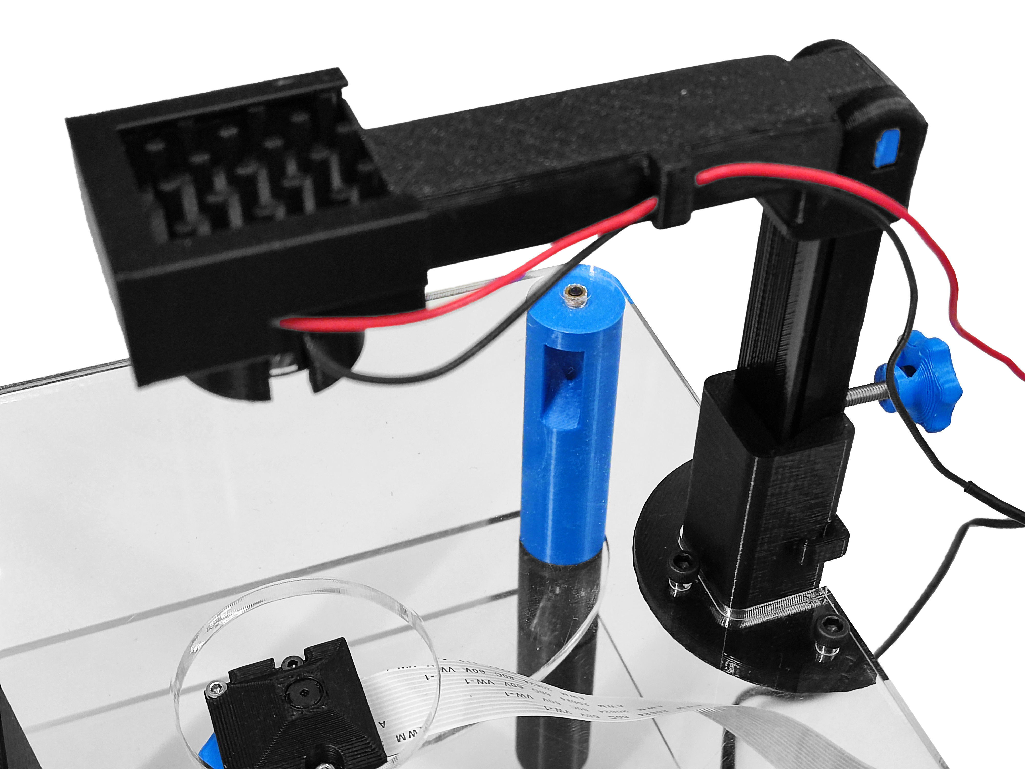
In this section, we are assembling the strobe illuminator. This mounts the high-power LED and condenser lens above the sample so the microscope can image the transmitted light.
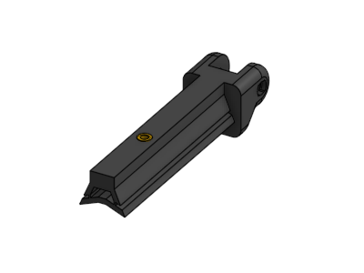
Step 1: Visually inspect the 3D parts
- Verify the slot of thumbscrew is clean. If strings of plastic are present, use a needle-nose plier to remove them.
- There should be a space between the thinner section and the body of the illumination slider. If not, use a plier to separate them.
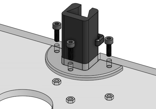
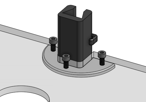
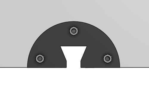
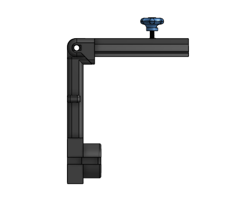
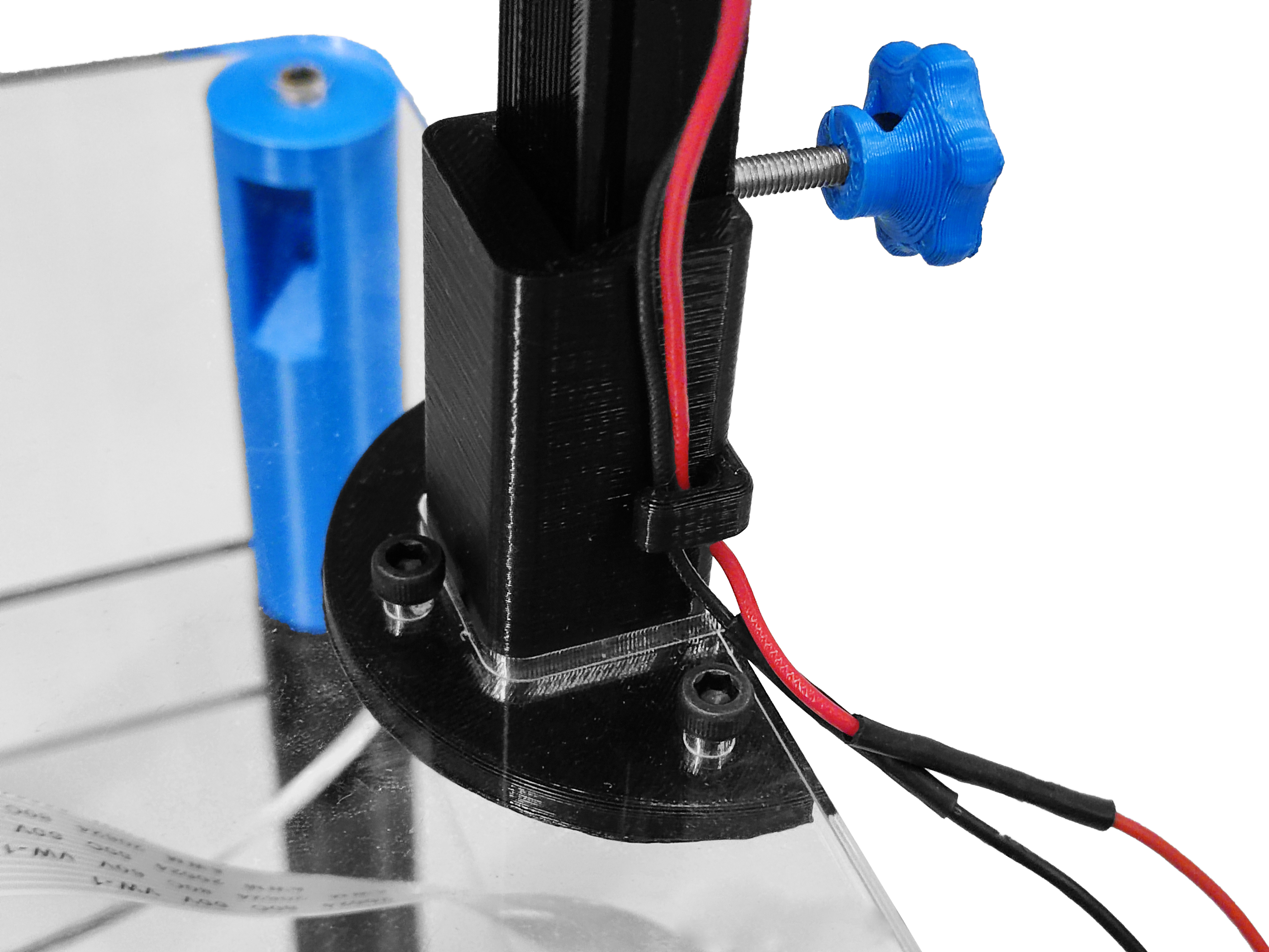
Step 2: Mount the base
- Place the illuminator base onto the top plate in opposite orientation to the focusing actuator.
- Secure in place with three M3x10mm screws and three M3 nuts (using a 2.5mm Ball-end Allen key)
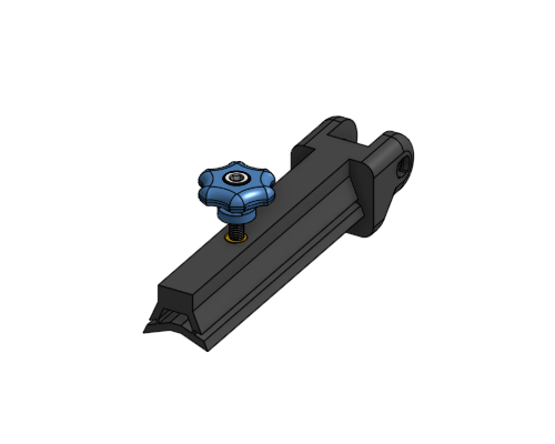
Step 3: Assemble the slider
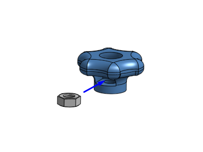
Illuminator thumbscrew
- Push a M3 nut into the slot in the illuminator thumbscrew.
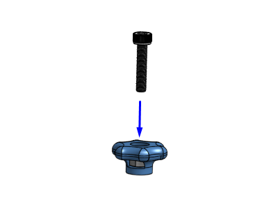
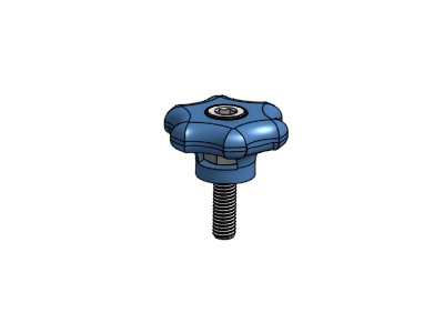
- Screw a M3x20mm pozi pan head screw into the thumbscrew. Use a #1 pozidrive screwdriver.
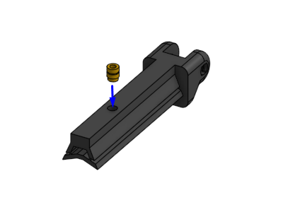
Illuminator slider
- Positionate a heat insert in the round hole of the illuminator slider
- Apply heat to the insert (using a soldering iron) and use gentle force to push it into position, as described in the guide to use heat inserts.
- Screw the thumbscrew assembly into the heat insert in the illuminator slider.
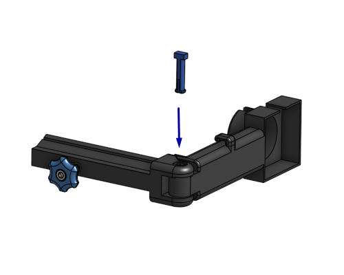
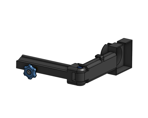
Step 4: Mount the light holder
- Put the illumination slider together with illumination arm, and align the holes.
- Use a hinge pin to connect them. Insert it into the rectangular side of the slider.
- It should take a little bit of force to push it through the holes. A needle-nose plier can be useful.
Step 5: Assemble the condenser lens, LED, and heatsink
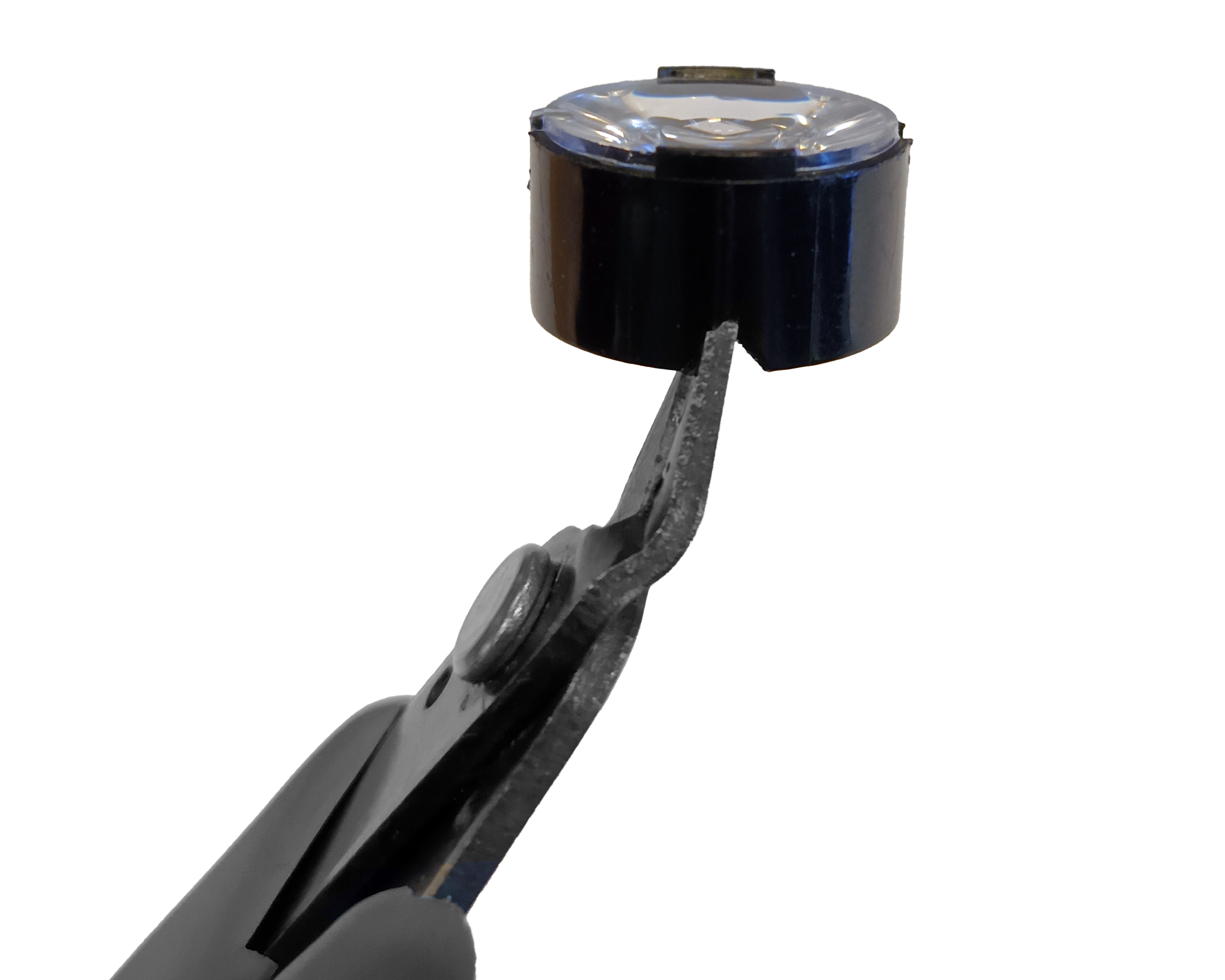
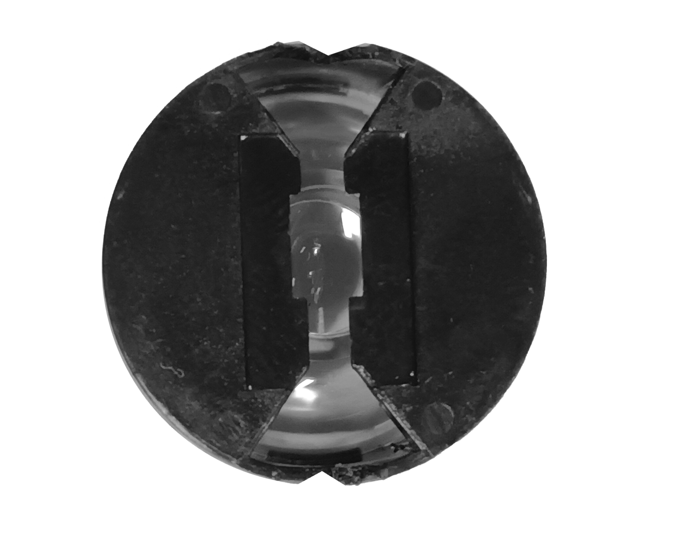
- Use nitrile gloves to manipulate the condenser lens.
- Make a V cut in the sides of the 20 mm circular lens using precision wire cutter as shown in the images.
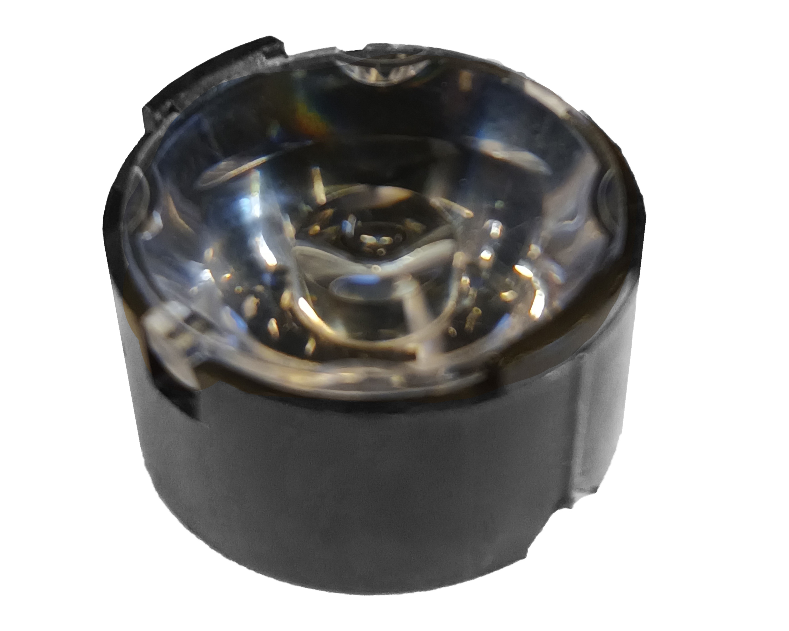
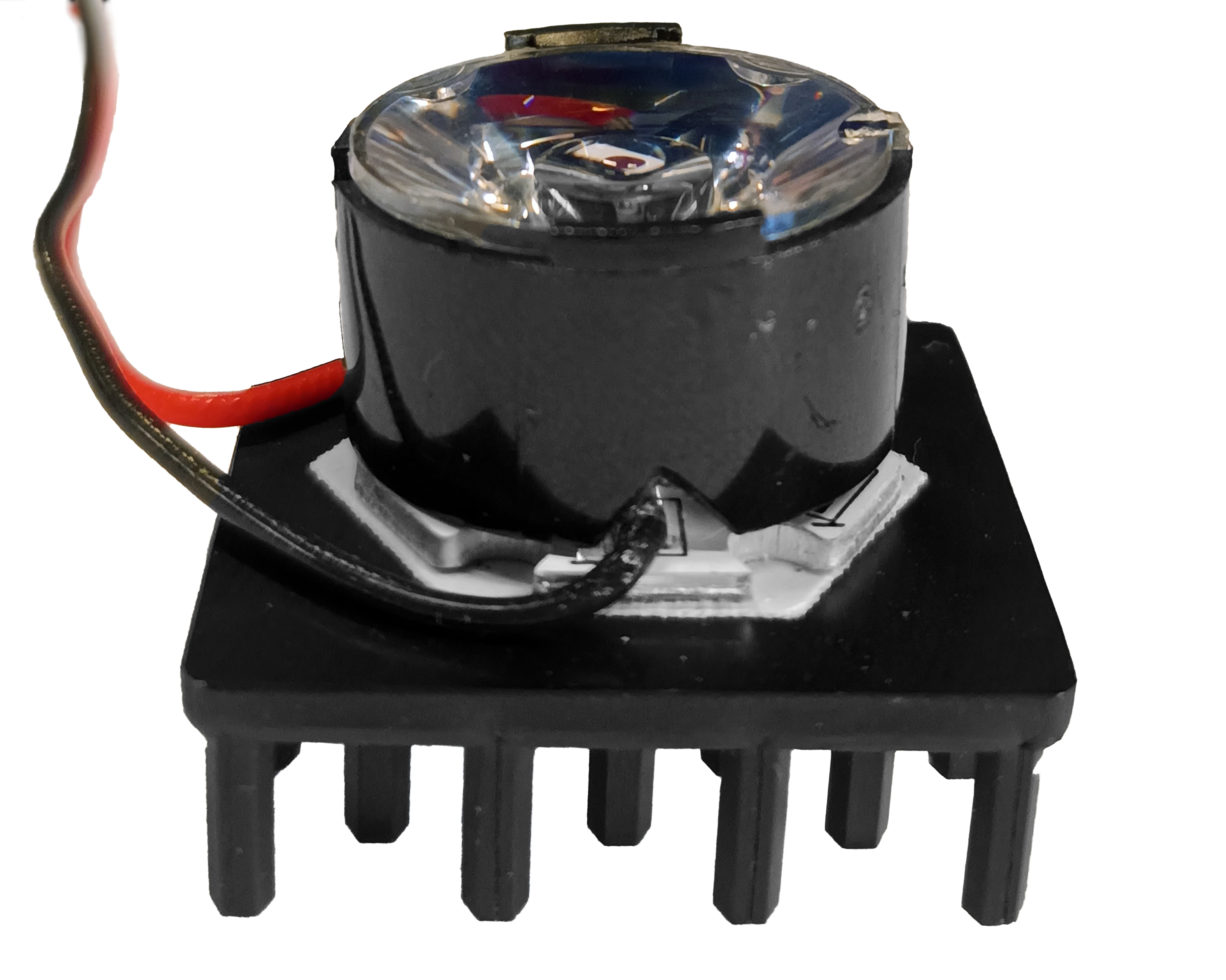
- Fasten a high-power LED to a heat sink using a double-sided thermal tape, as described in this guide.
- Fasten the assembly to a 20 mm circular lens using a double-sided self adhesive tape, as described in this guide.
- The final assembly should be as shown below.
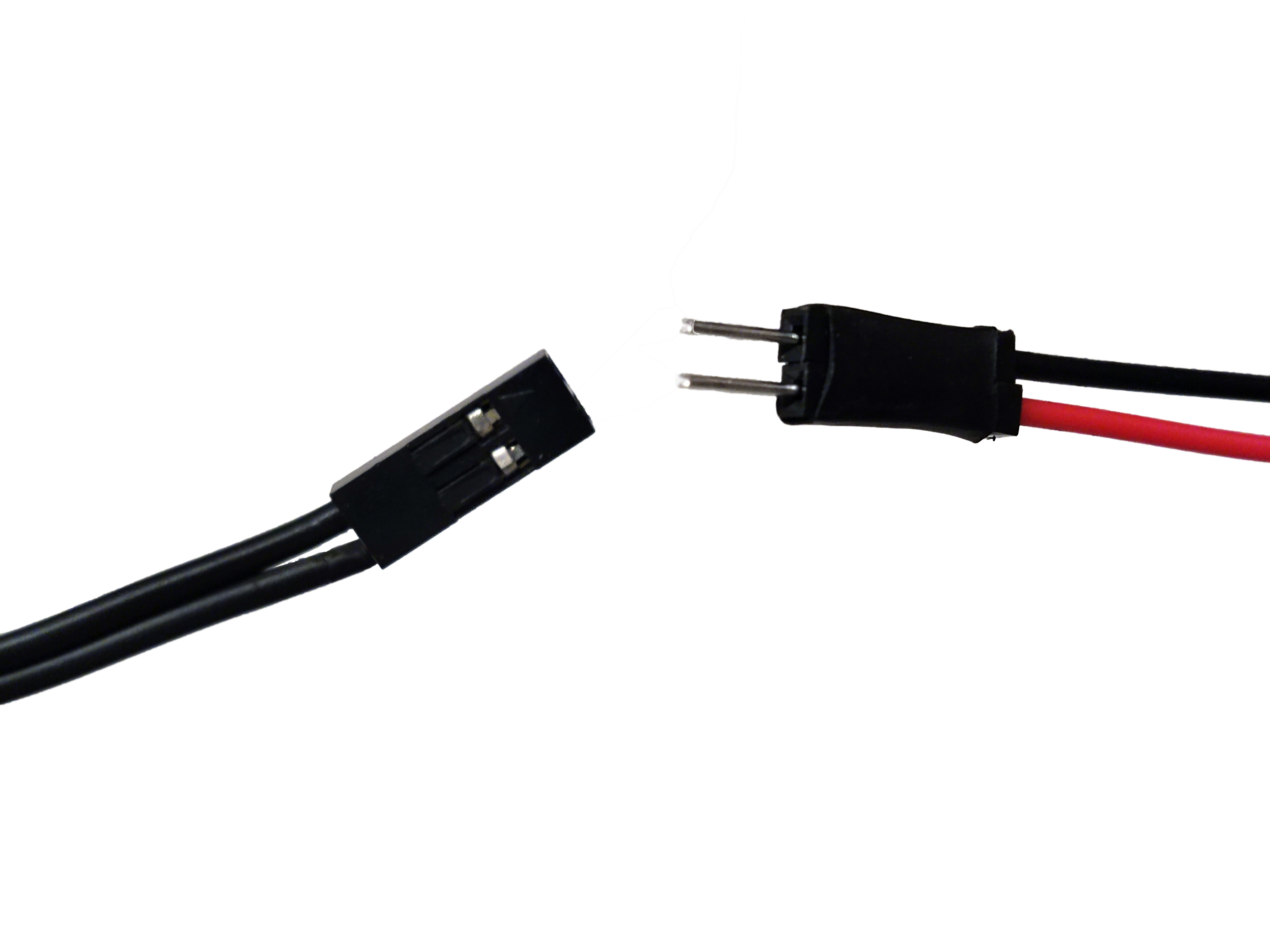
Step 6: Assemble the illumination wiring
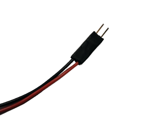
- Take the red and black cables of the illumination assembly and crimp them using two male connectors and a crimper as described in this guide.
- Attach a 2 pin Du Pont connector female housing to it.
- The illumination wiring should be as shown below.
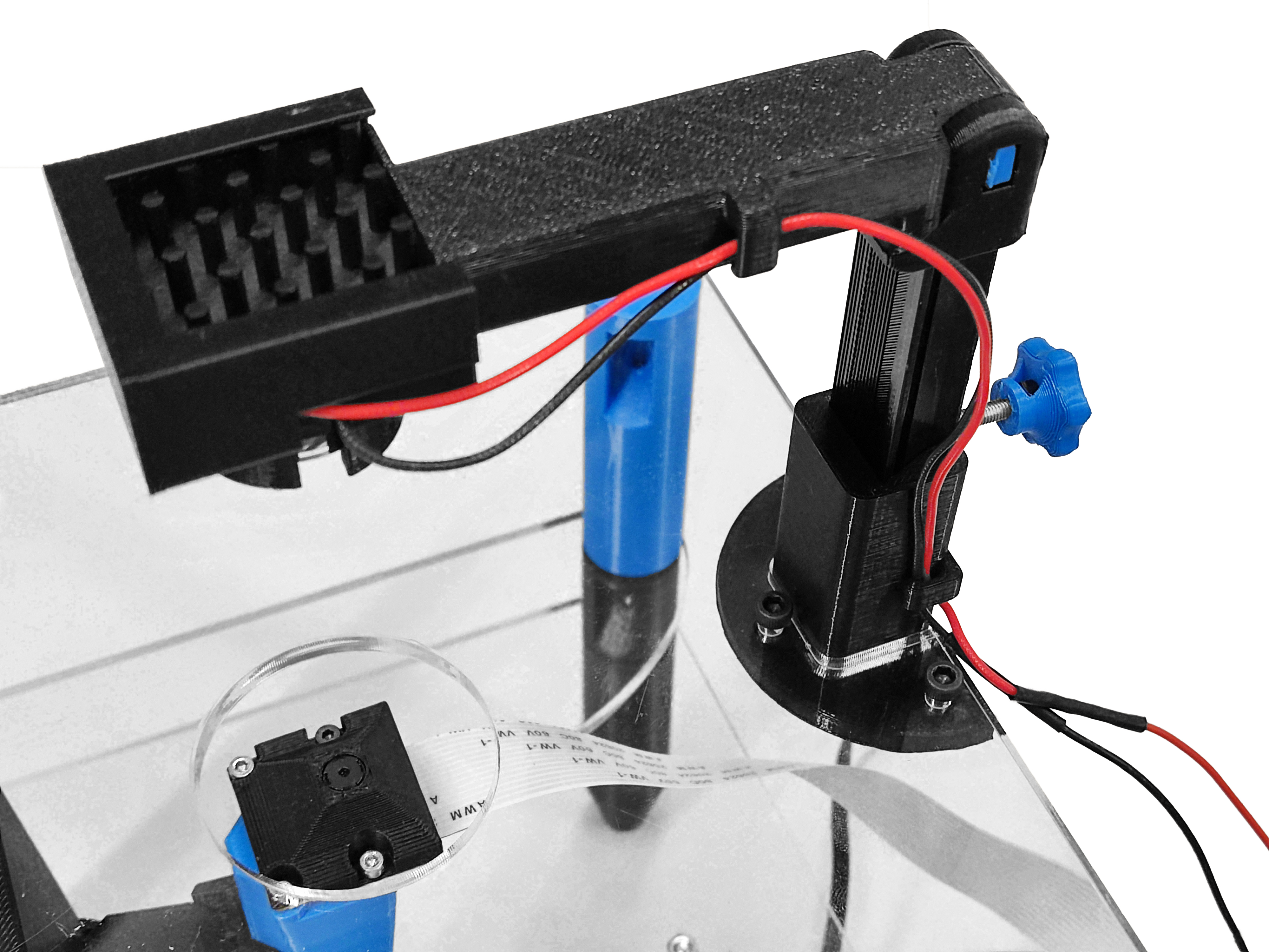
Step 7: Mount the illumination assembly
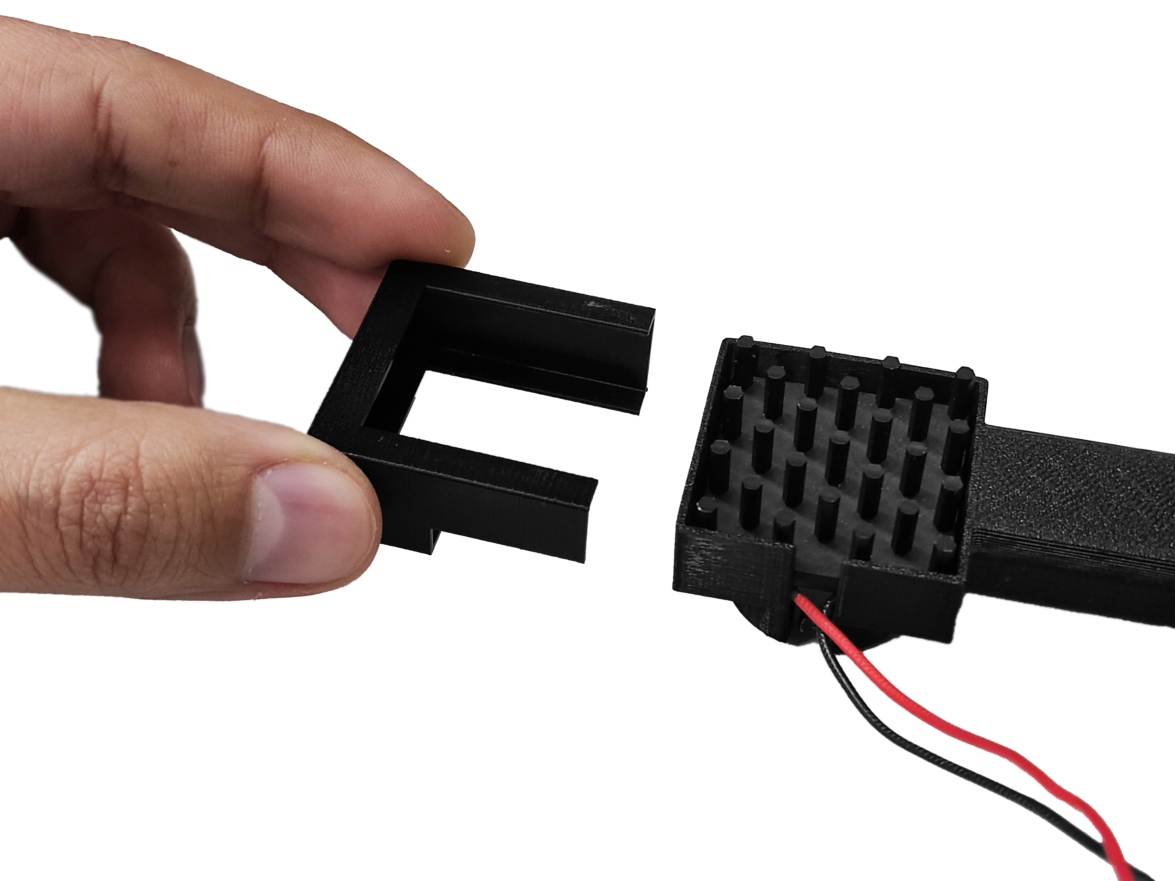
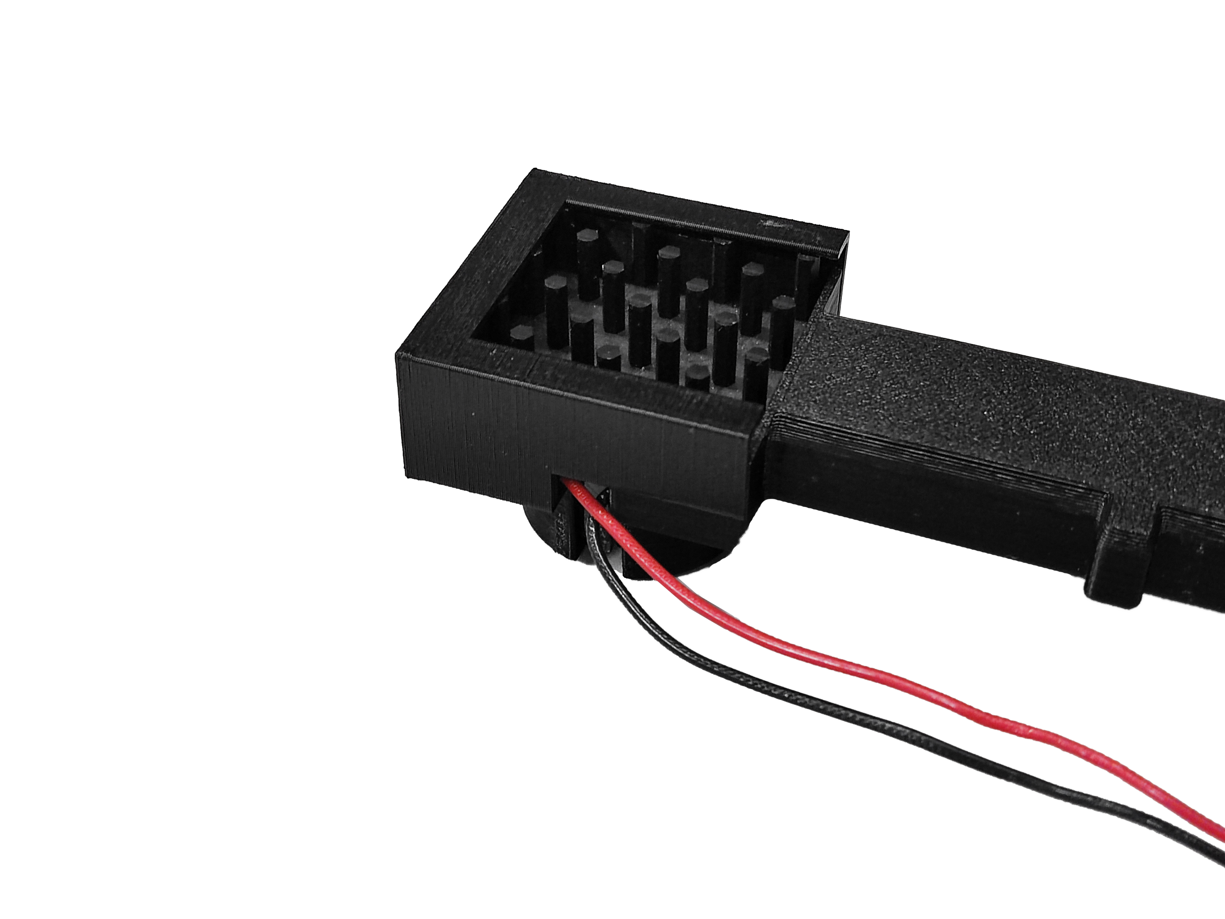
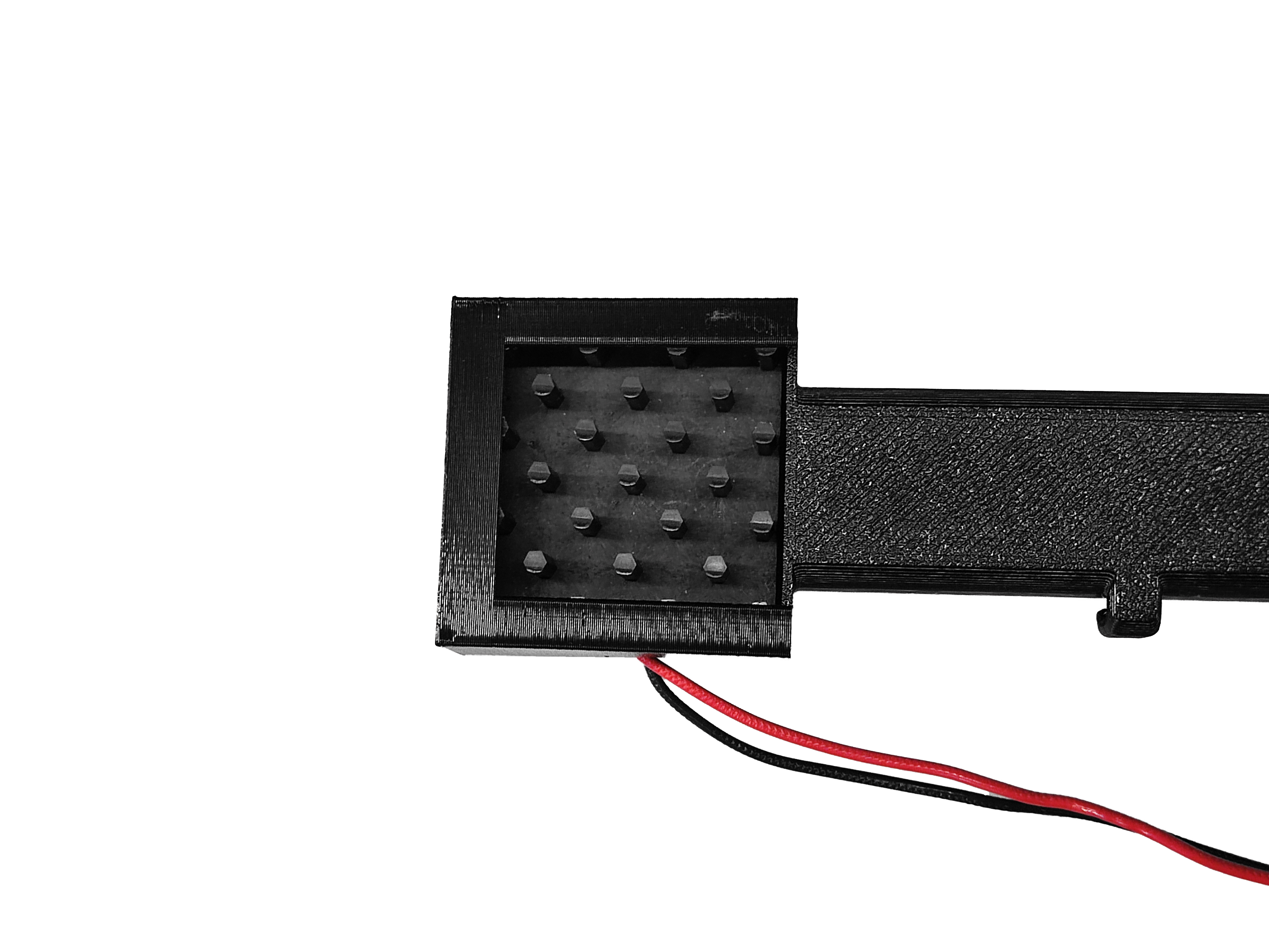
- Position the illumination assembly in the illumination arm. One side of the LED holder has a space for cables.
- Secure the assembly using a cover, which also have a space for cables.
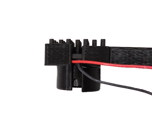
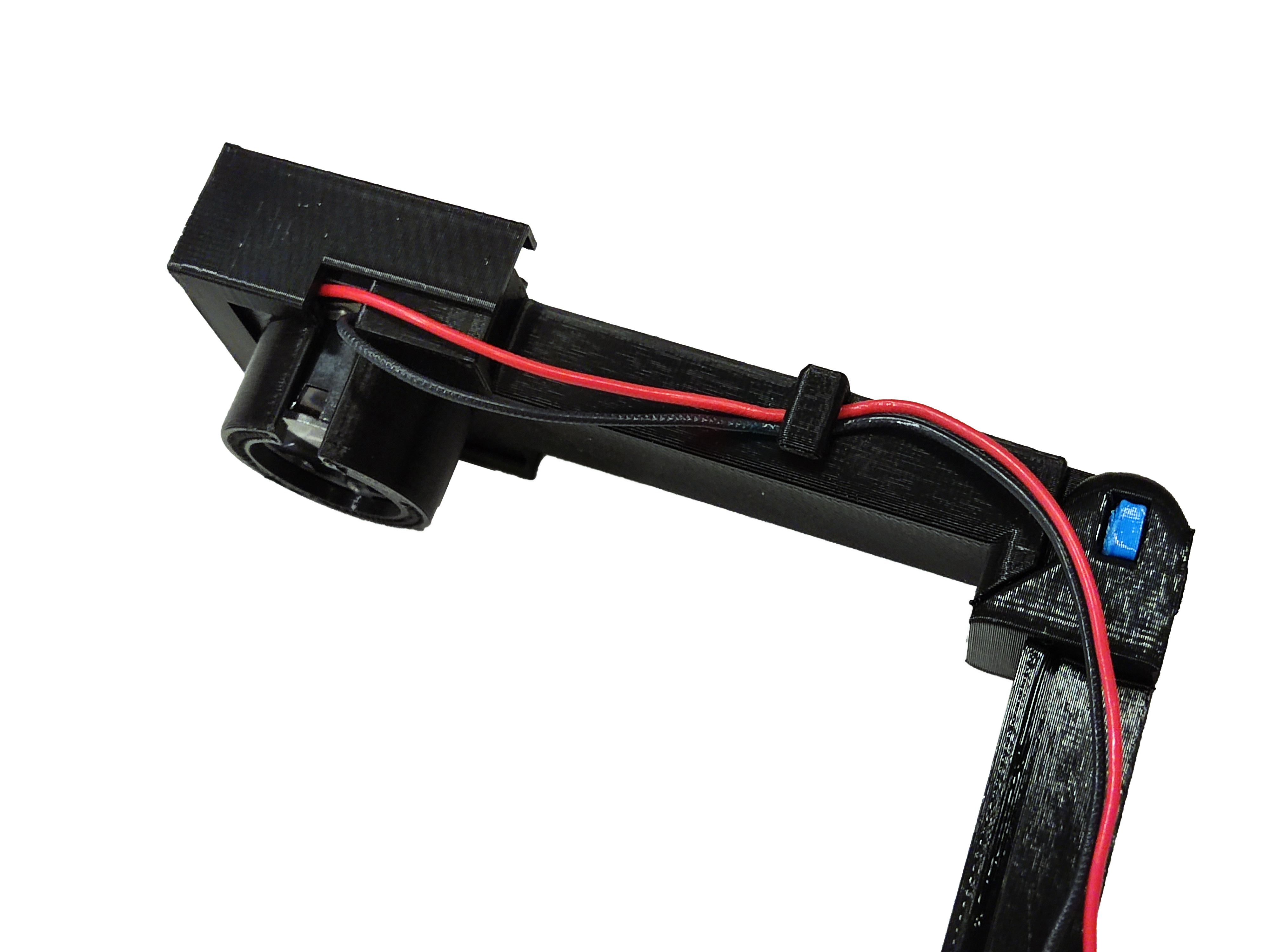
Step 8: Attach the illumination wiring
- Insert the illumination wiring to the cable clip next to LED holder
- Mount the illumination arm assembly to the base.
- Insert the illumination wiring to the other cable clip in the base.
Step 9: Connect the strobe
- Connect DuPont female 2-pin connector of the strobe cable to the 2-pin male connector of the illumination wiring. Be careful to connect positive and negative terminals in wrong position.