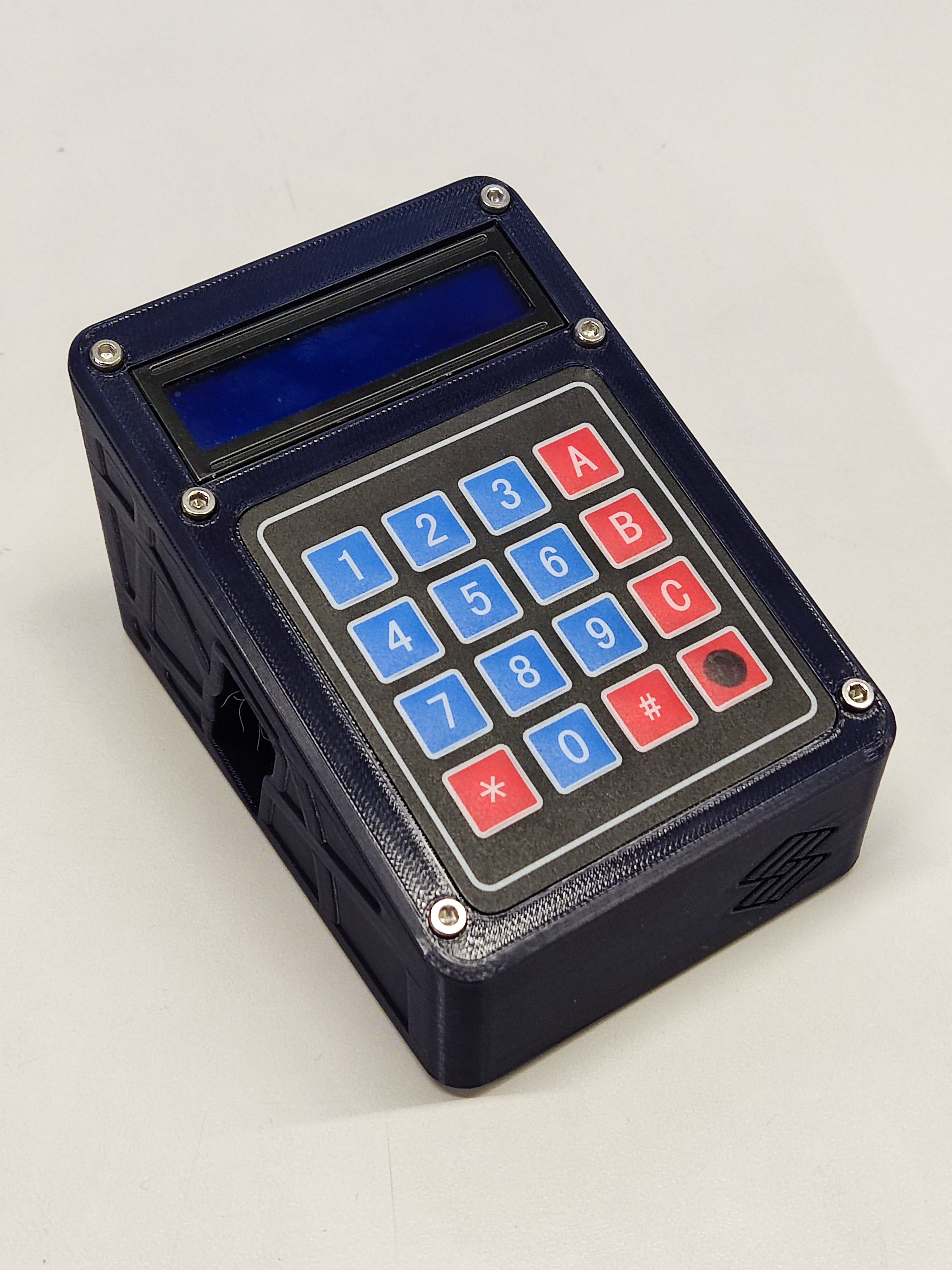
ESP32 controller assembly
For this section you will need:
Tools
Electronic Components
- 4 10 cm female-female jumper
- 1 Alligator clip wire
- 1 ESP32-WROOM-32D
- 1 LCD screen
- 1 Membrane 4x4 keypad
- 1 PCB controller
- 1 Power supply 12V 6A
- 2 TMC2226 driver
Mechanical Components
- 10 Heat insert
- 10 M3 10mm screw
Printed Parts
- 1 Base
- 1 LCD spacer
- 1 Lid
Step 1: Prepare the base of the controller
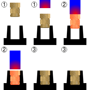
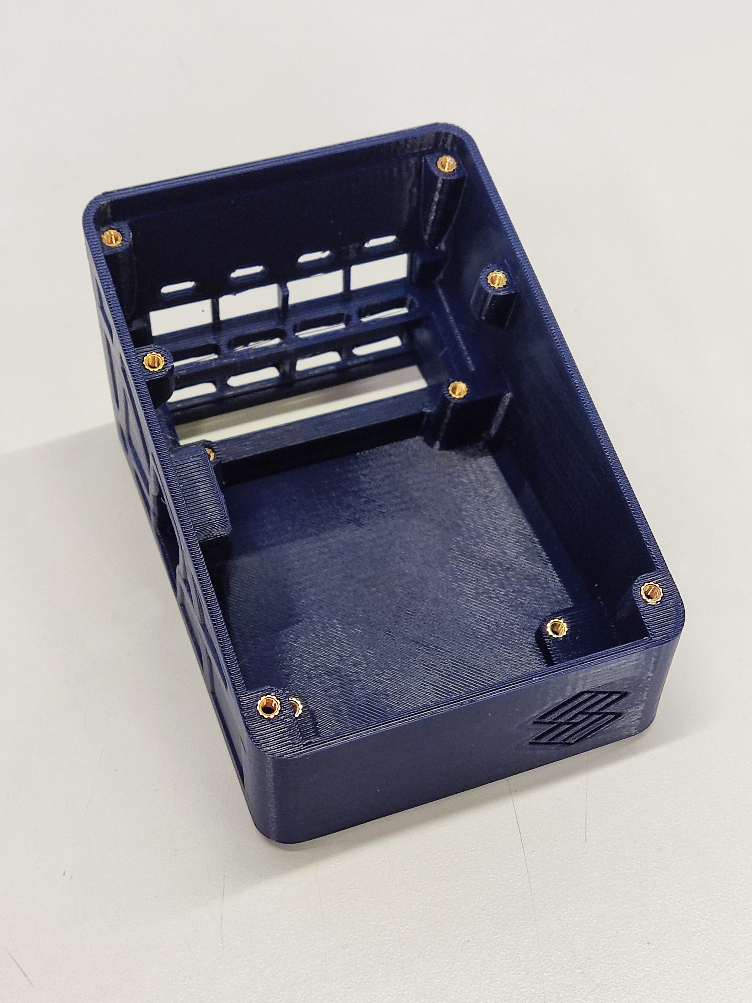
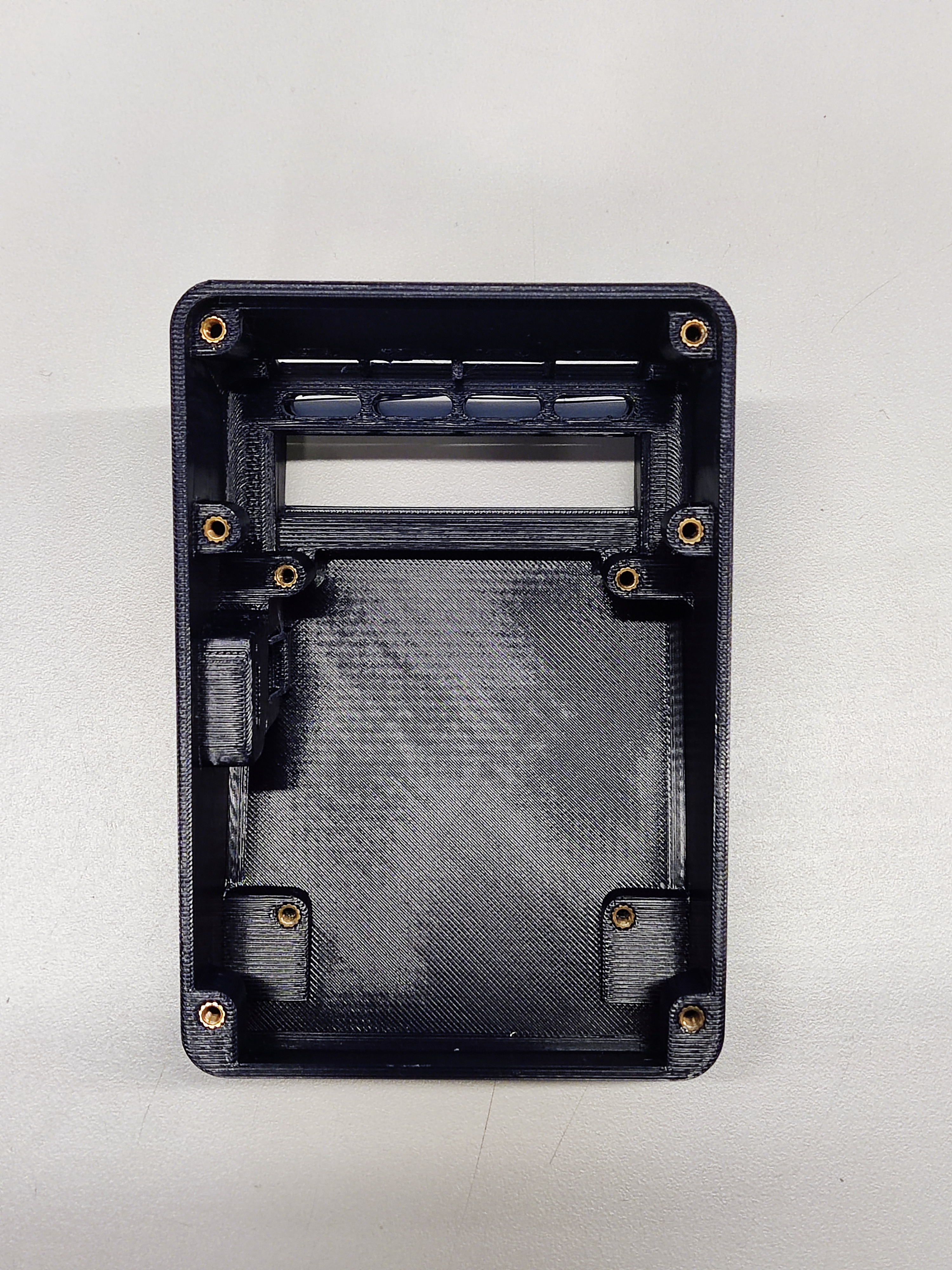
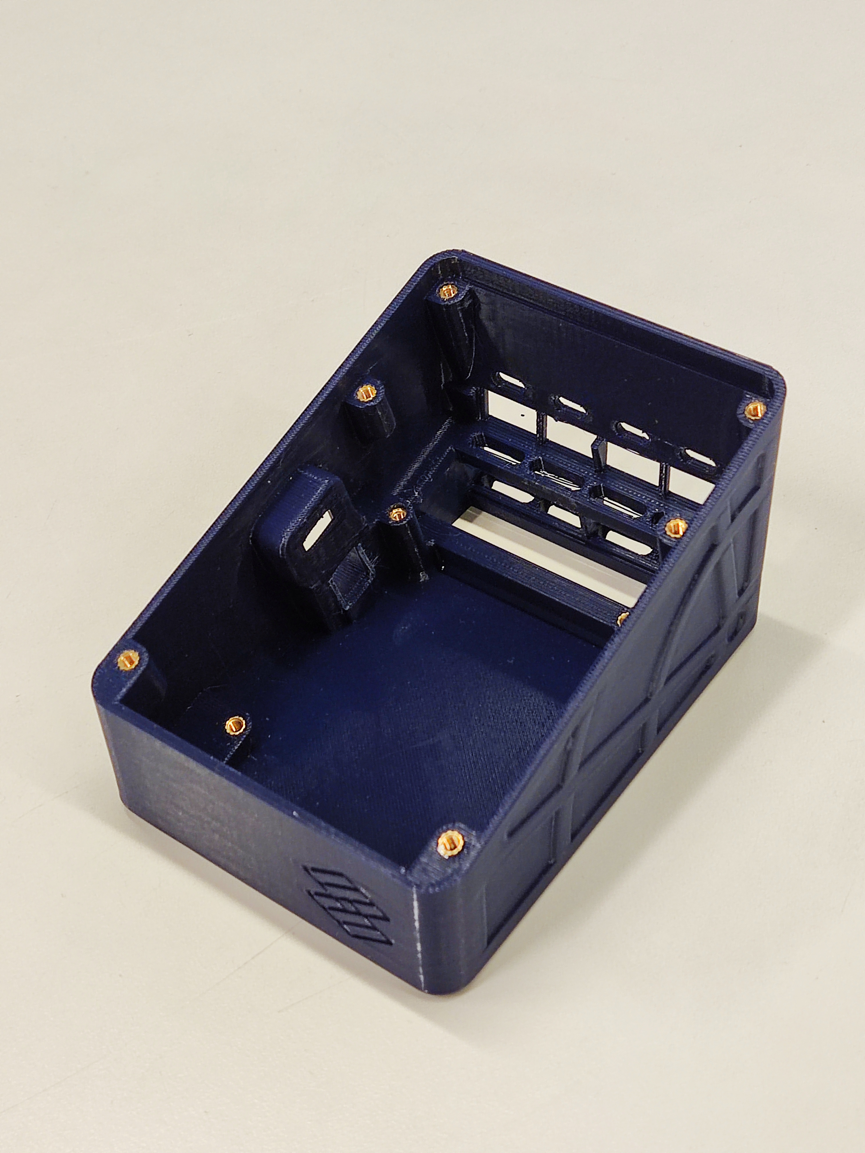
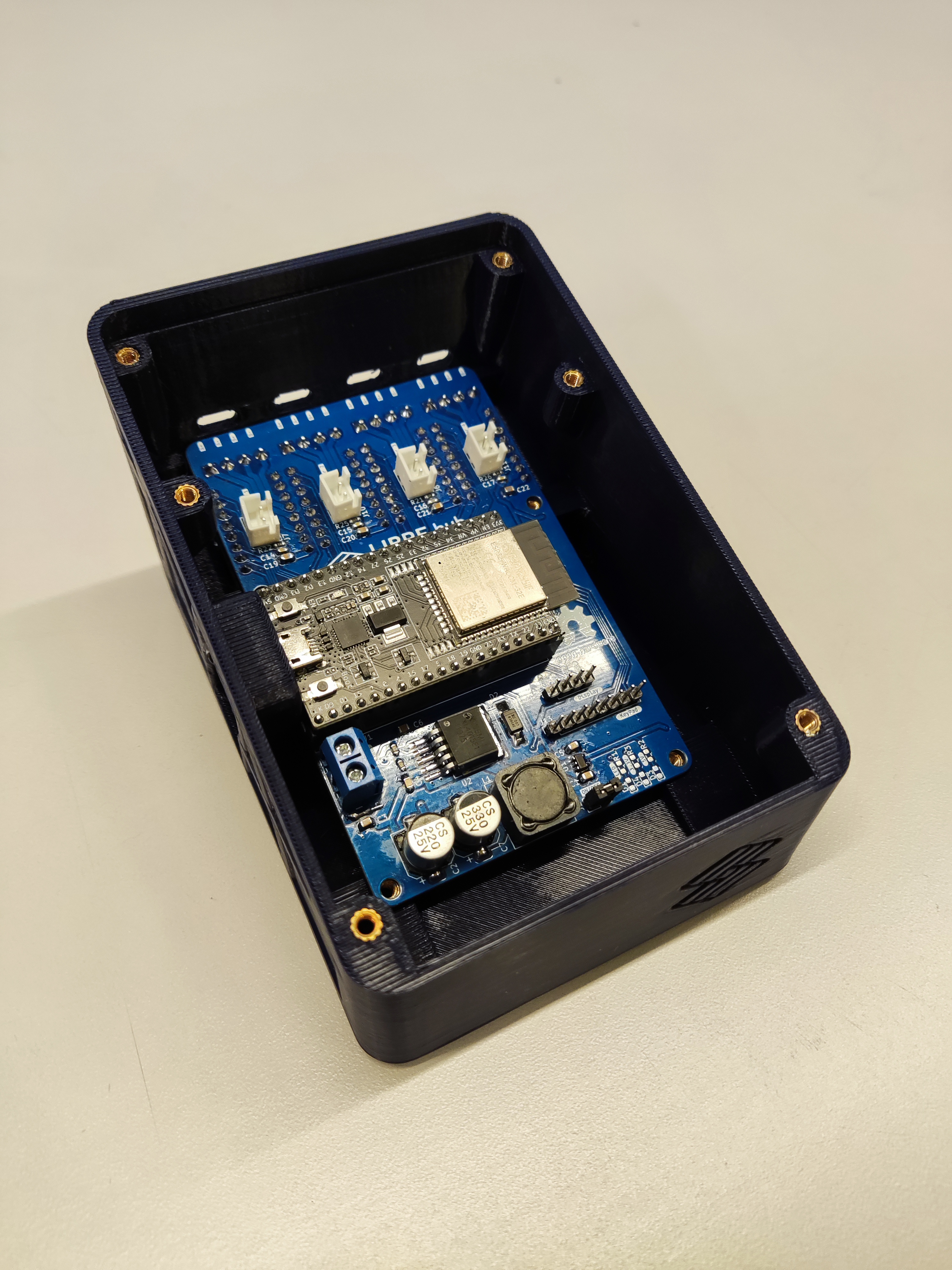
Grab the base, take ten heat insert and position them in each hole of this printed part. Apply heat to each insert (using a soldering iron) and use gentle force to push it into position, as described in the guide to use heat-set inserts.
Step 2: Mount and configure the motor drivers
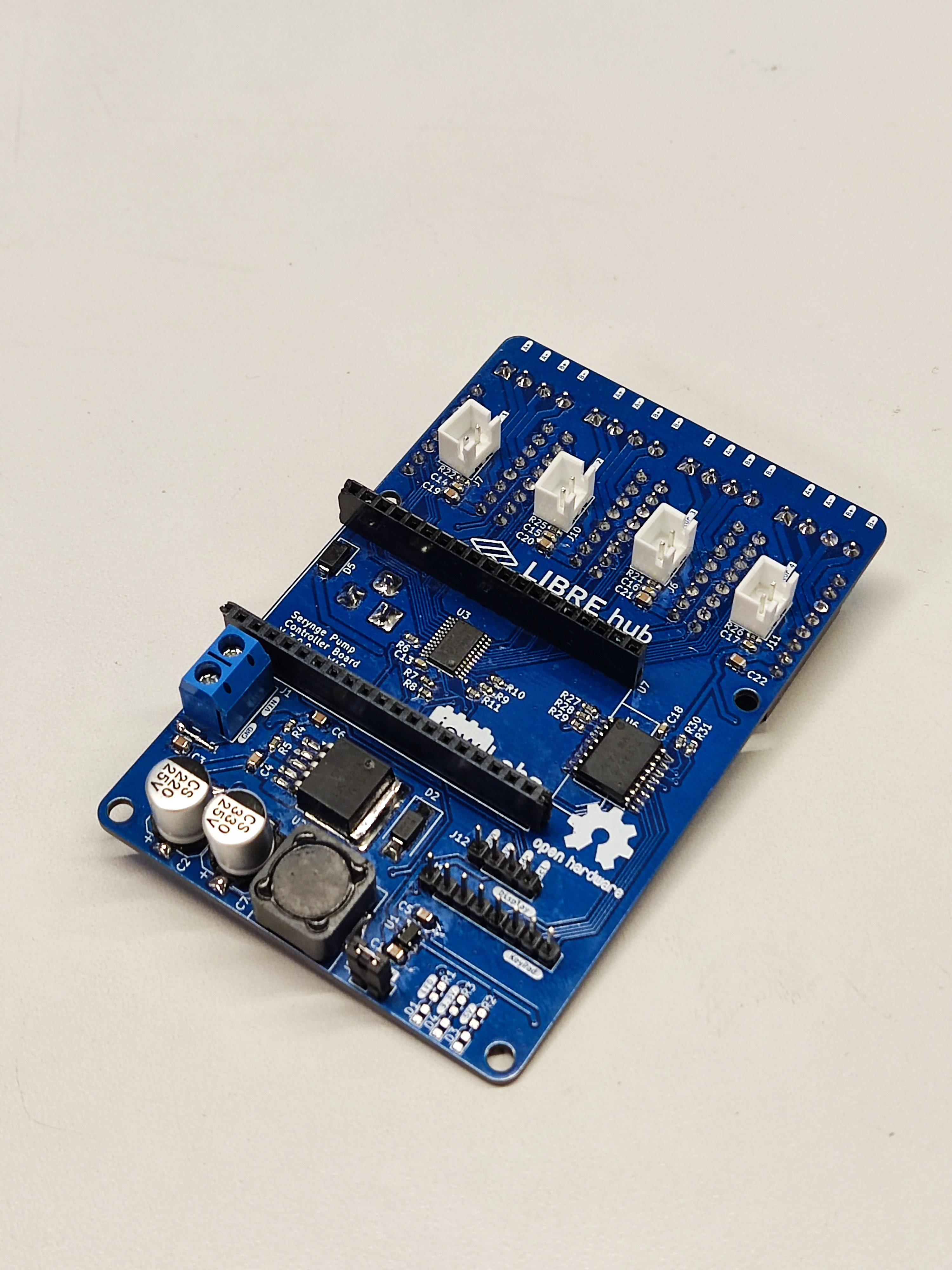
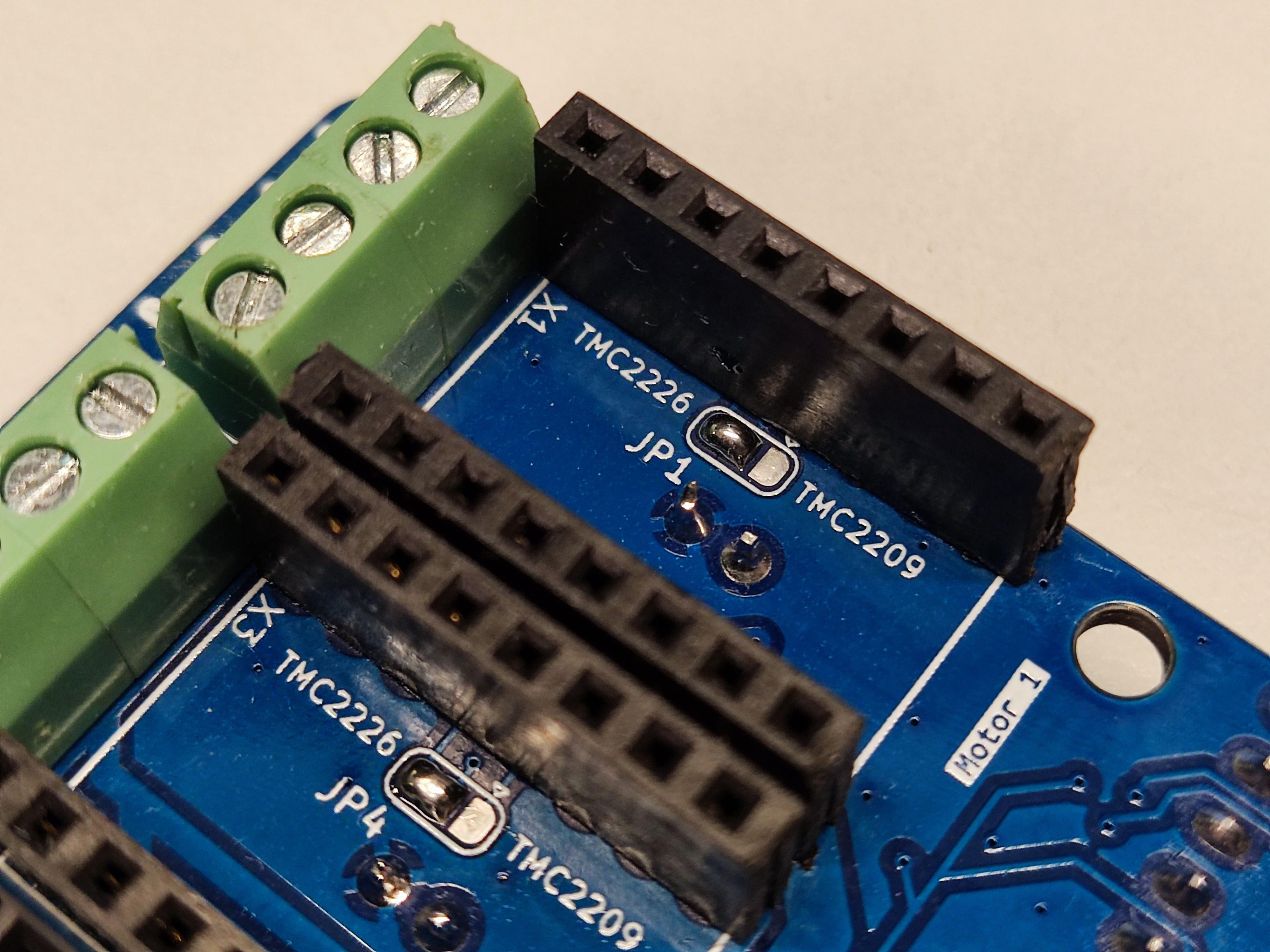
Before mounting the drivers, verify the PCB configuration is compatible with your driver model. Take a TMC2226 driver and mount it to the driver port on the back of the PCB controller.
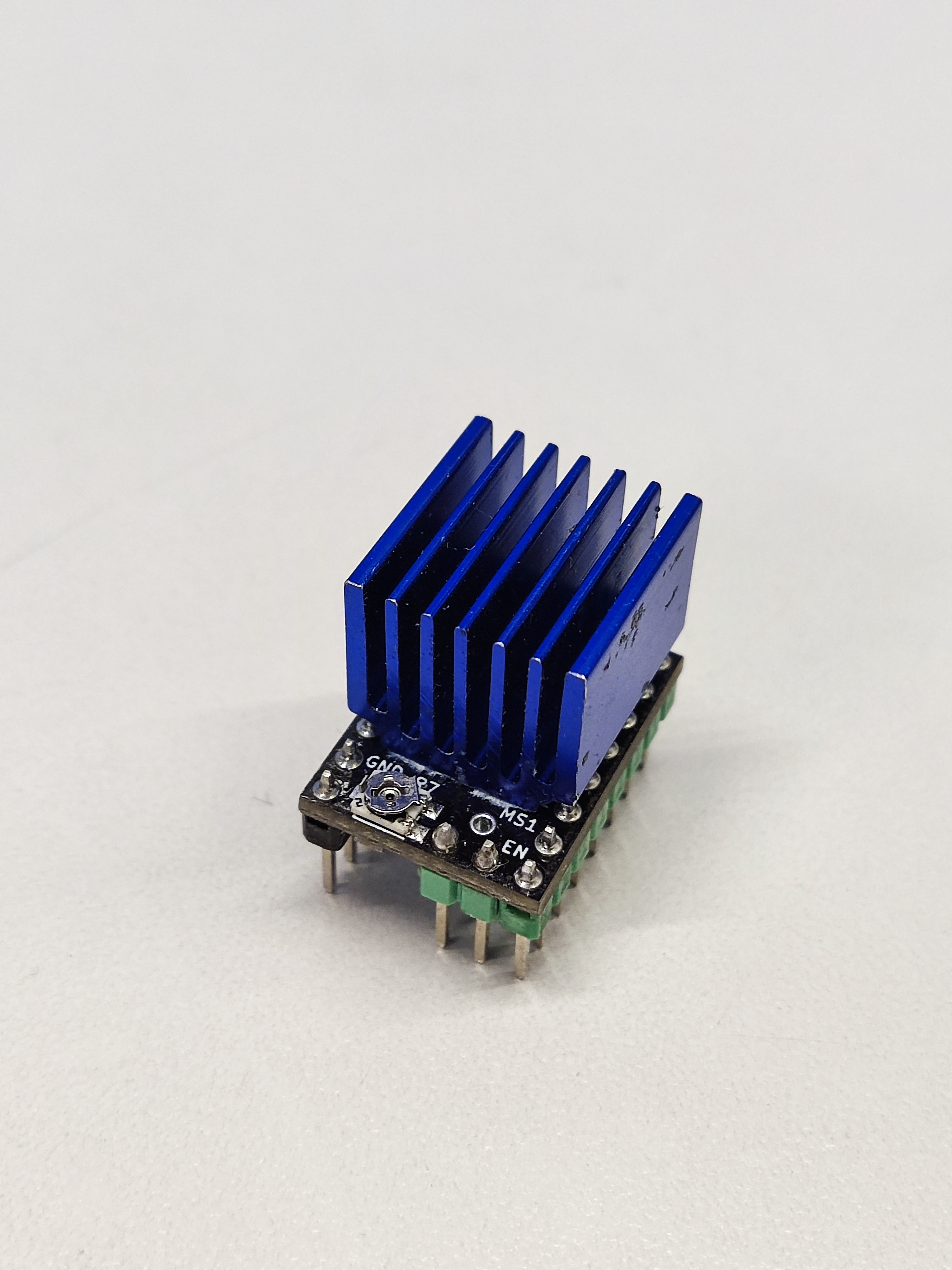
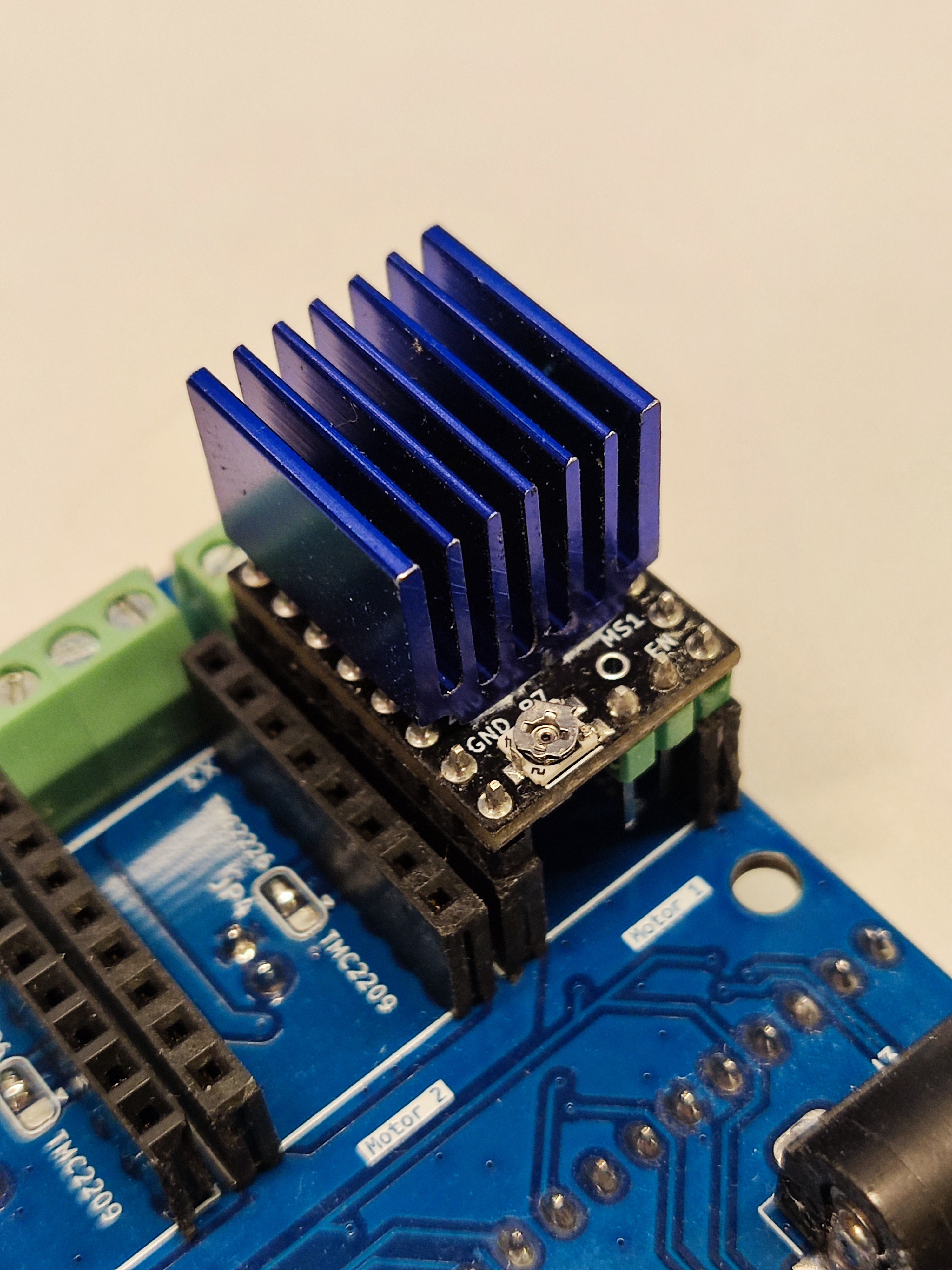
Then, configure the voltage reference (Vref) of your driver to supply the appropriate current to your motor model. Check the datasheet of your motor to determine the appropriate current rating.
Connect a 12V/6A power supply to the power port of the PCB controller. As shown in this tutorial, take a multimeter, a precision screwdriver, and an alligator clip wire to measure and set the voltage across the Vref pin of the driver. This value will determine the maximum current that the driver can supply to the motor.
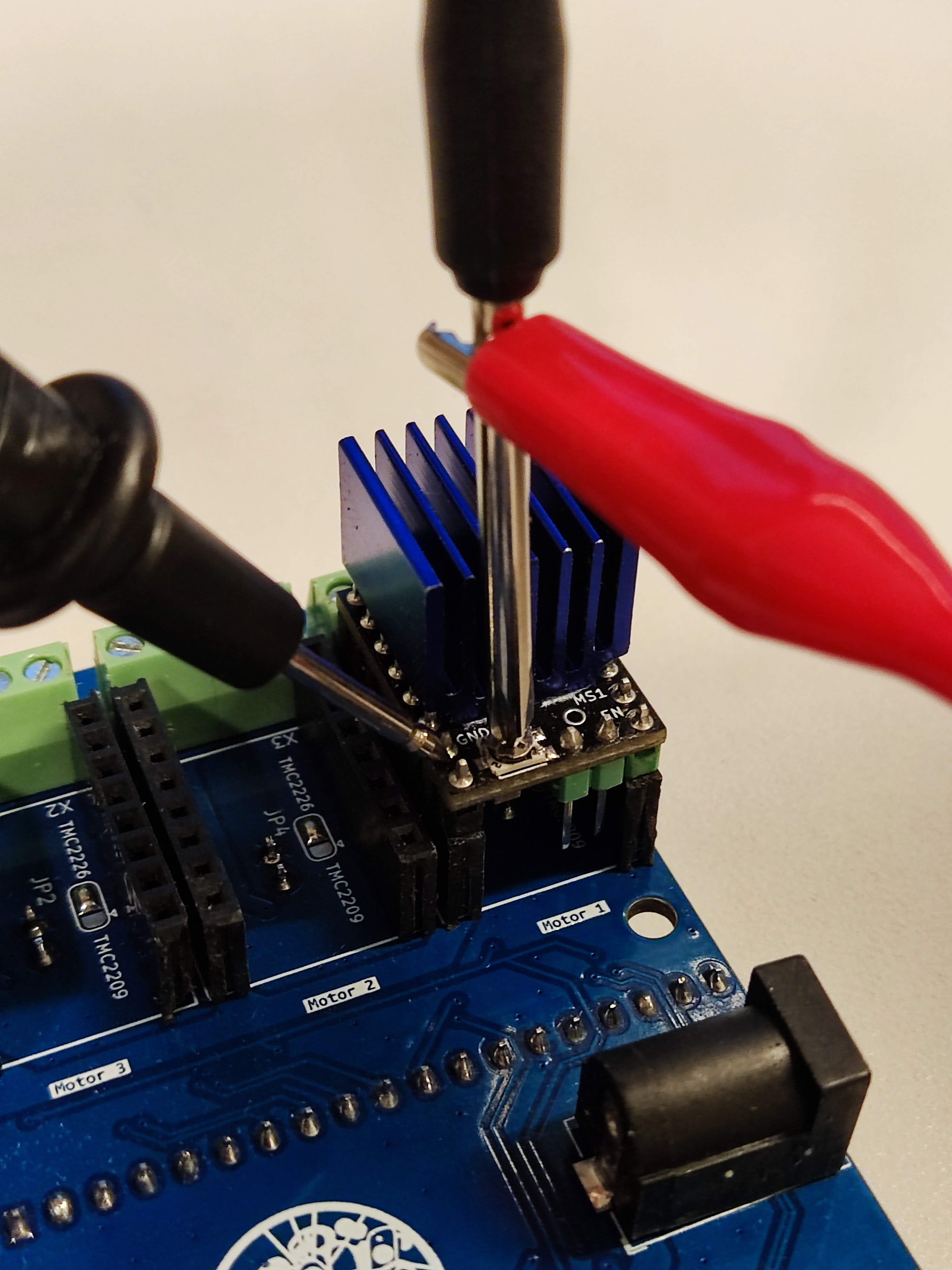
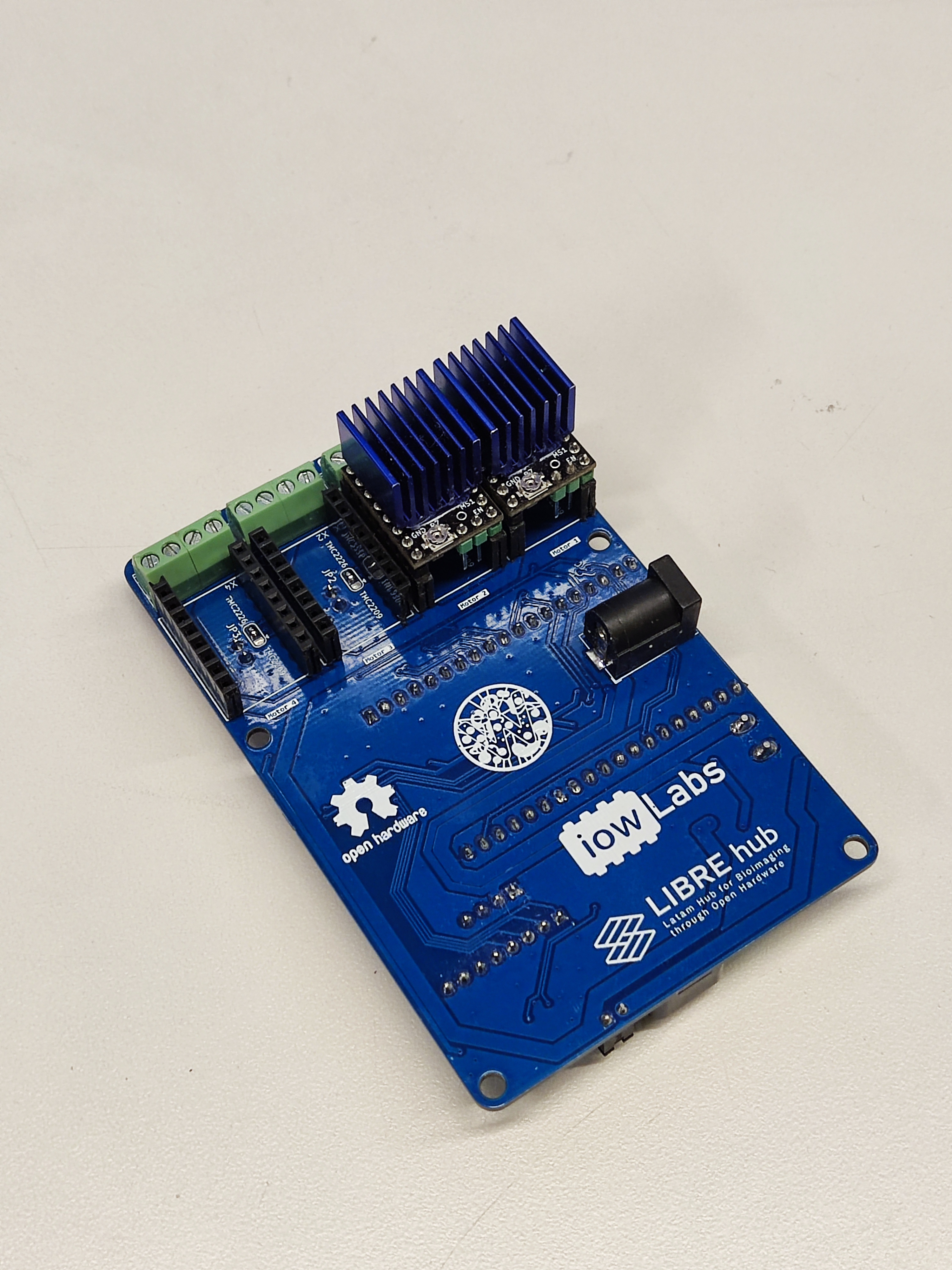
Repeat this step for every driver you will mount in your controller.
Step 3: Mount ESP32 microcontroller and PCB
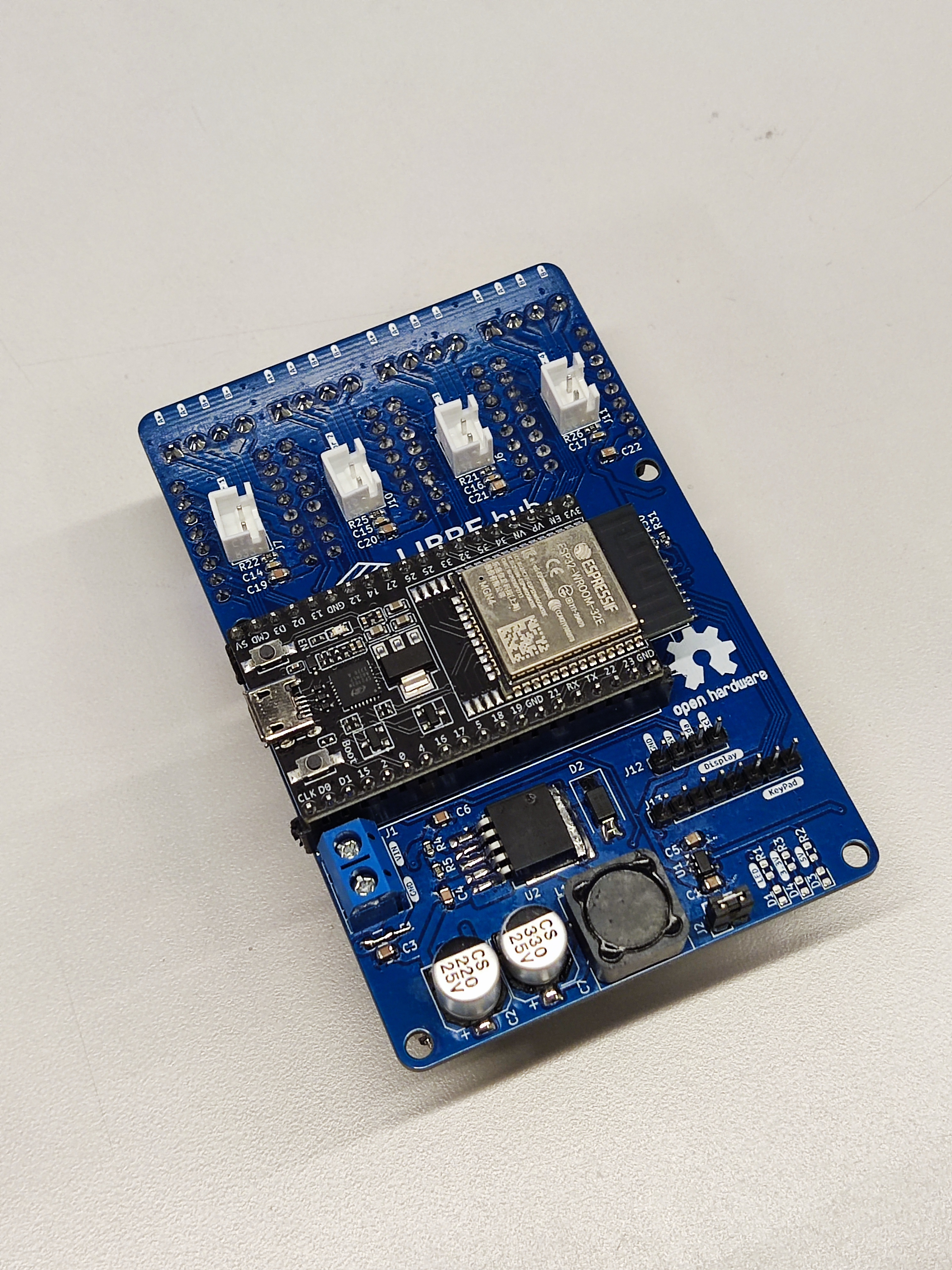
Take the ESP32 microcontroller and mount it to the PCB controller.
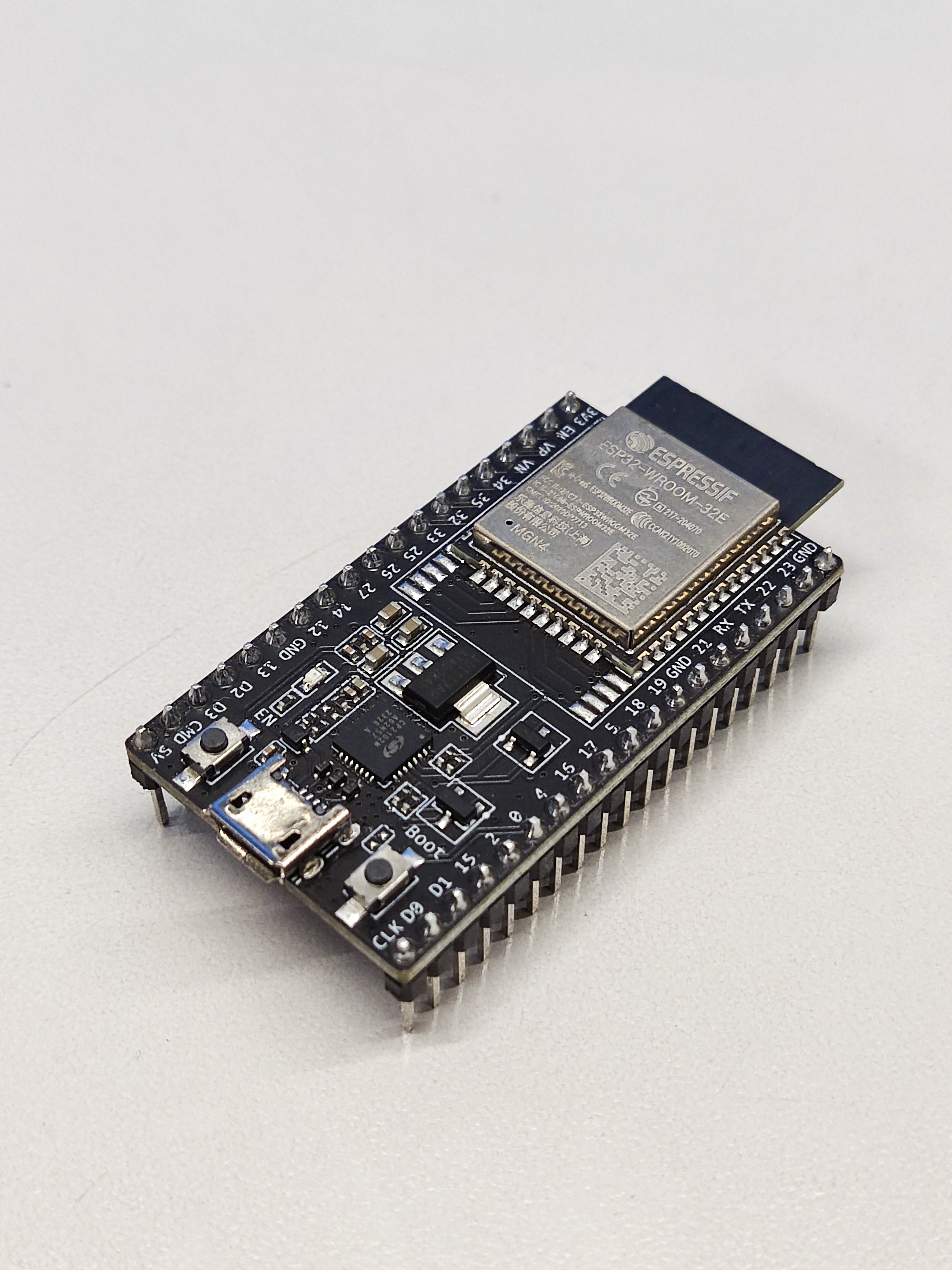
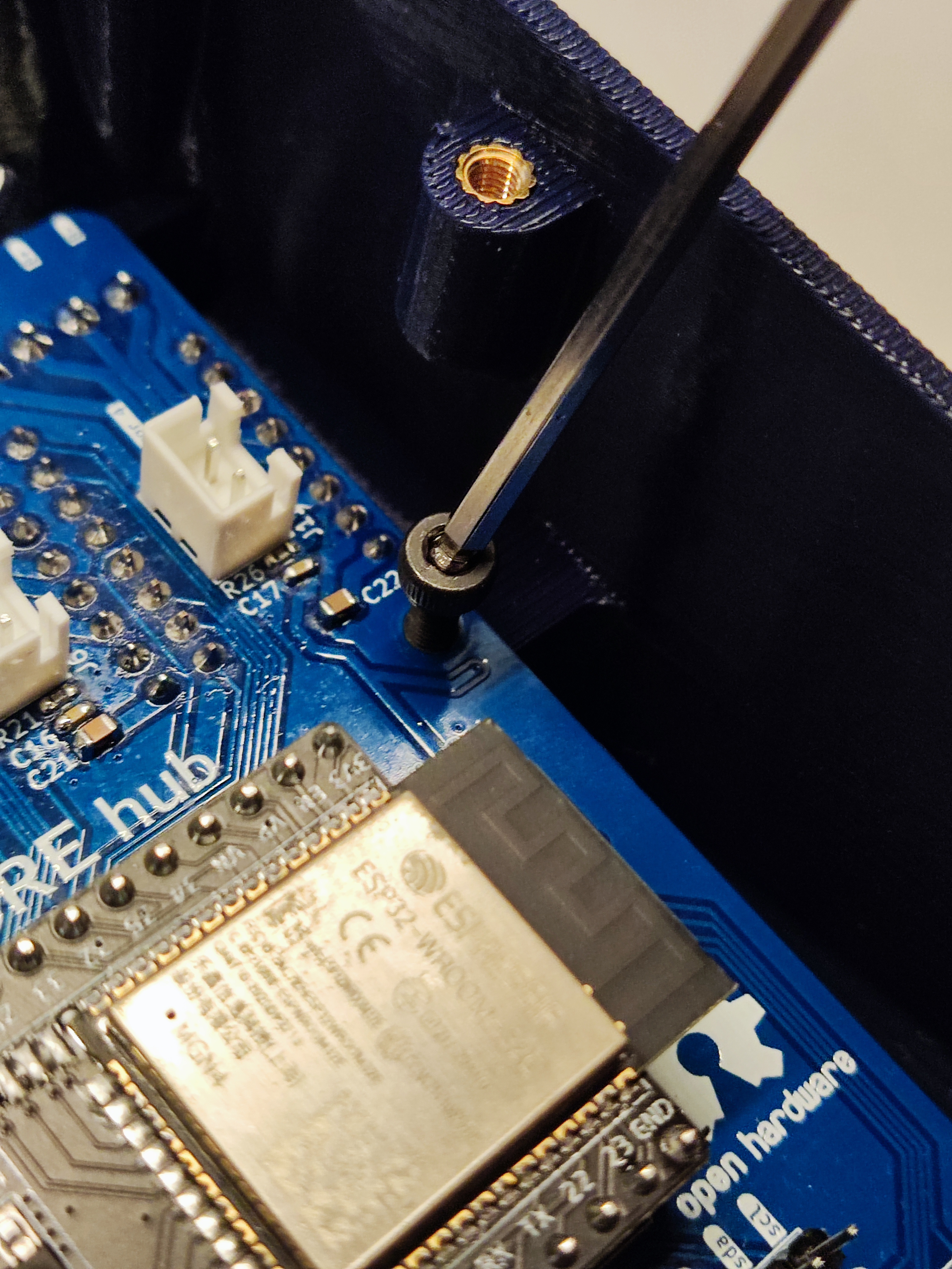
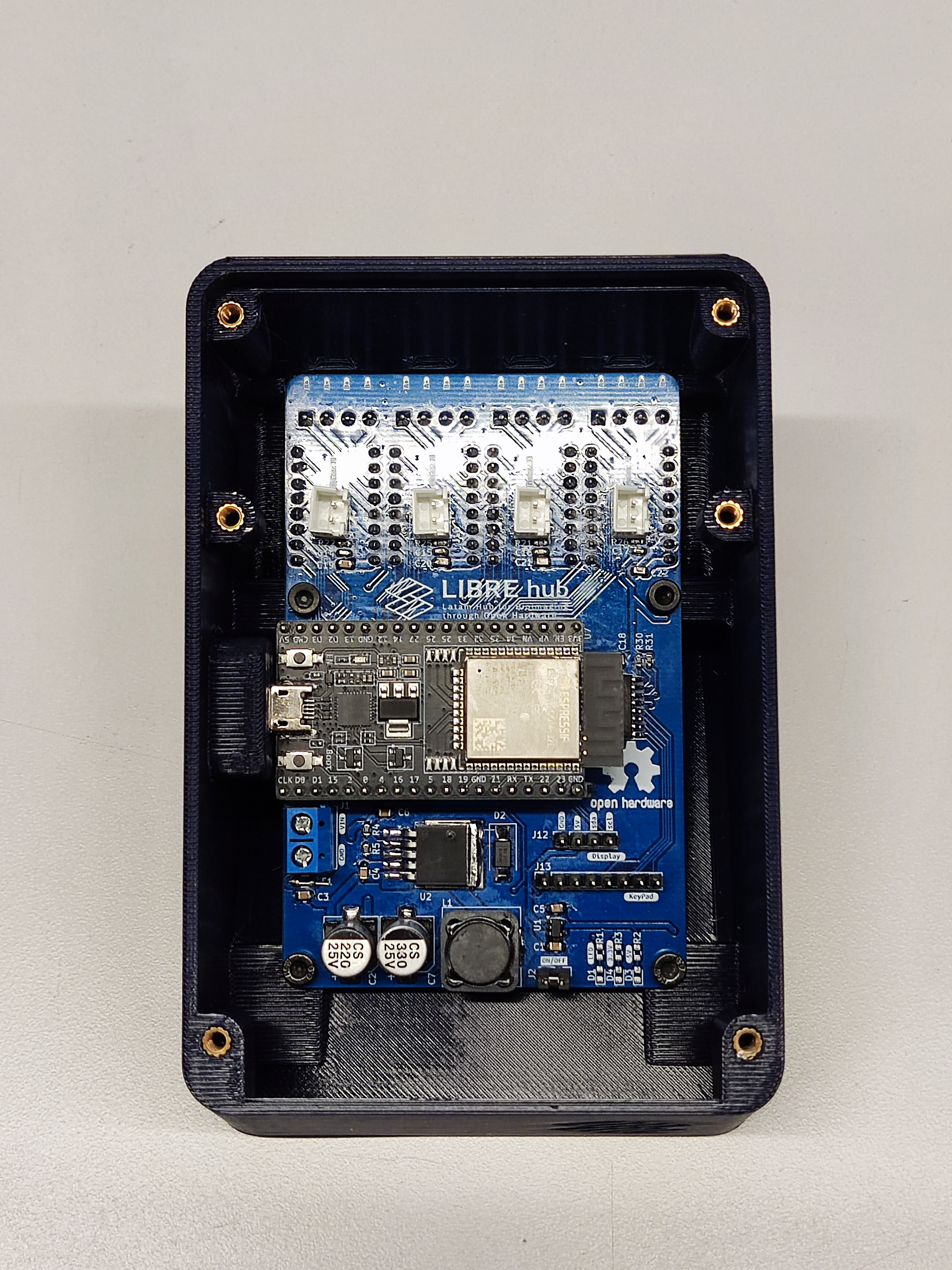
Place the PCB controller on the base and mount it by using four M3 10mm screws.
Step 4: Connect the LCD and keypad
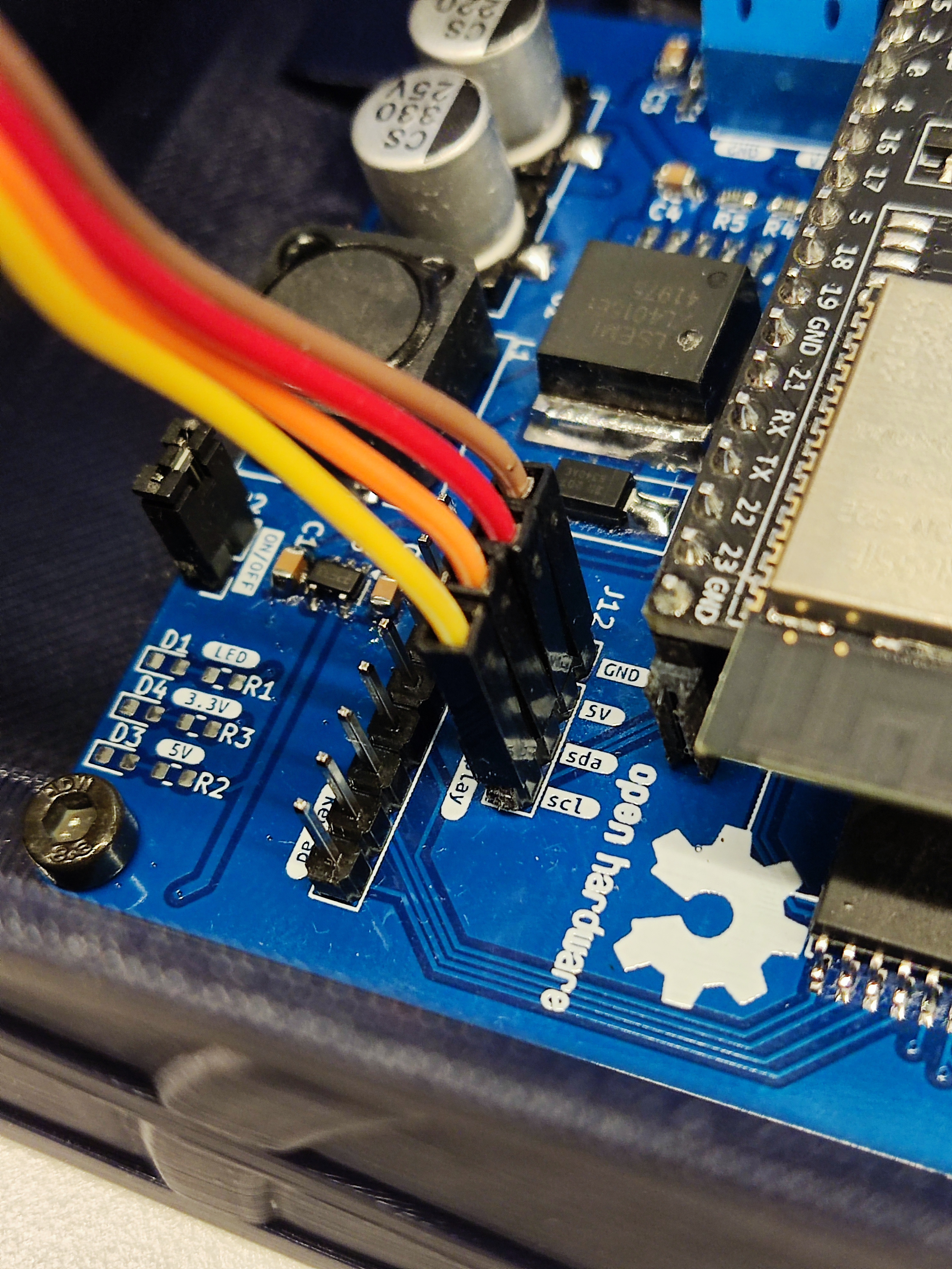
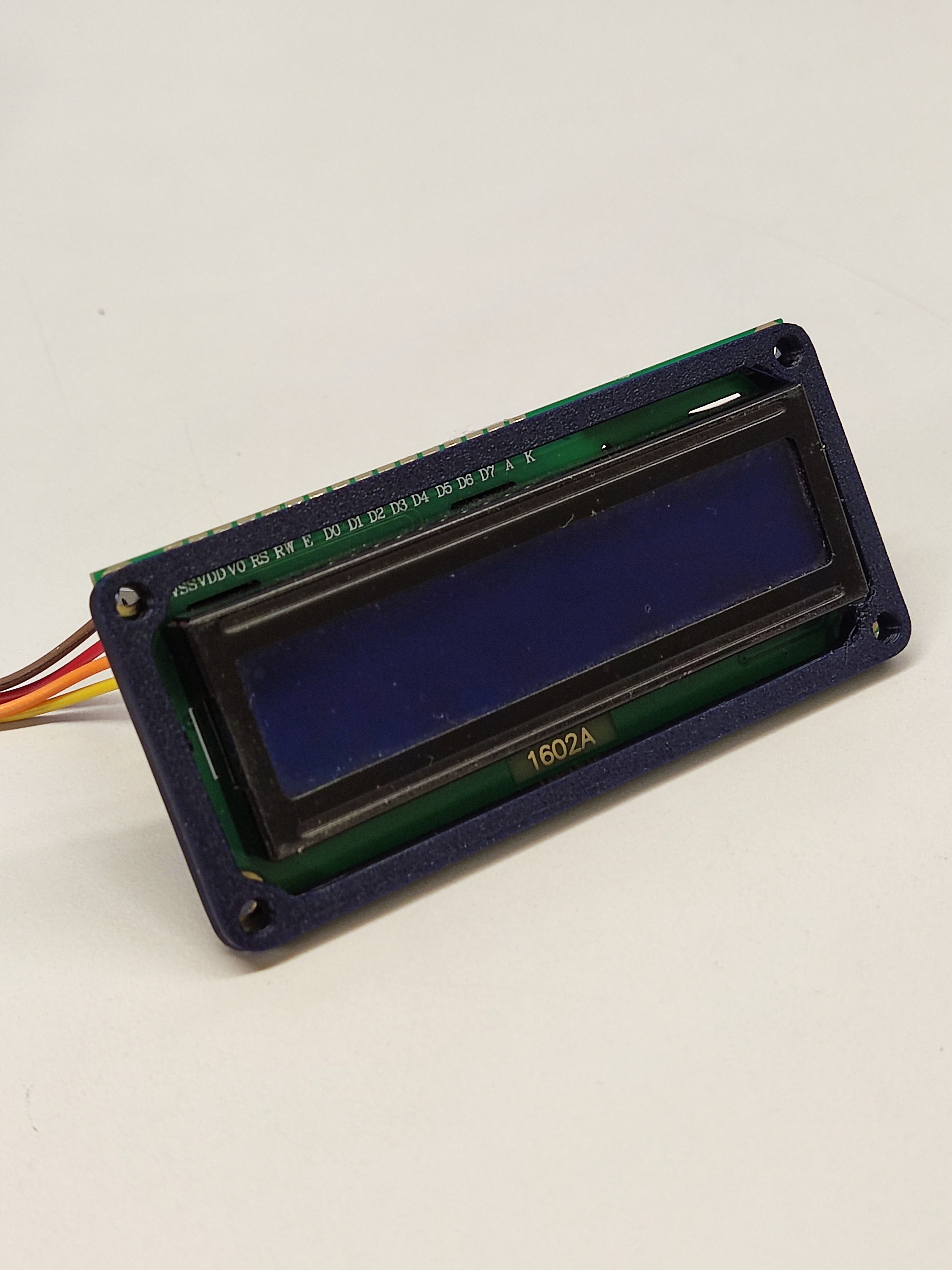
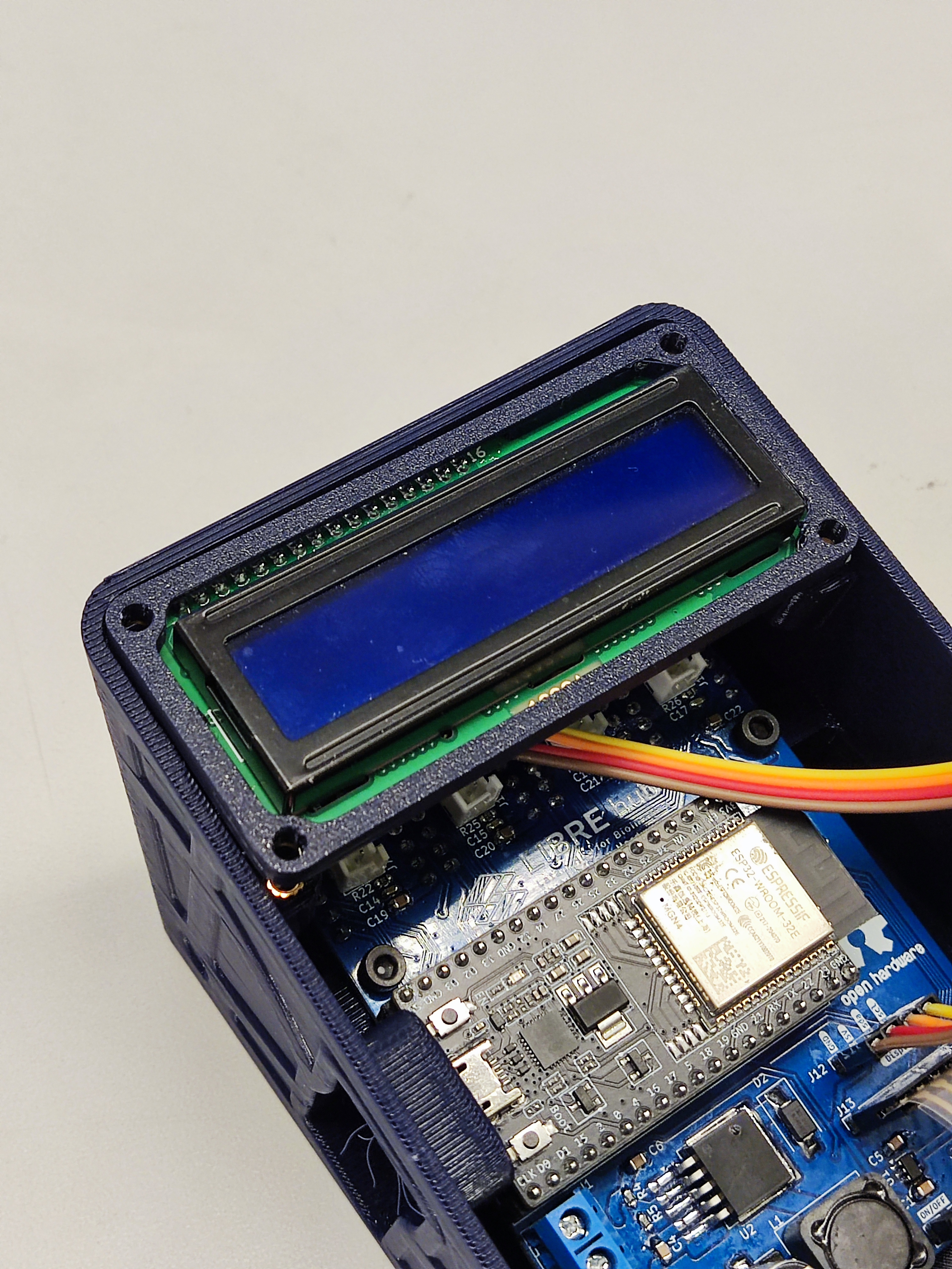
Take the LCD and connect four female-female wires to its pins. Then, connect the wires to LCD pins on the PCB controller, verifying they match with the pins from the LCD.
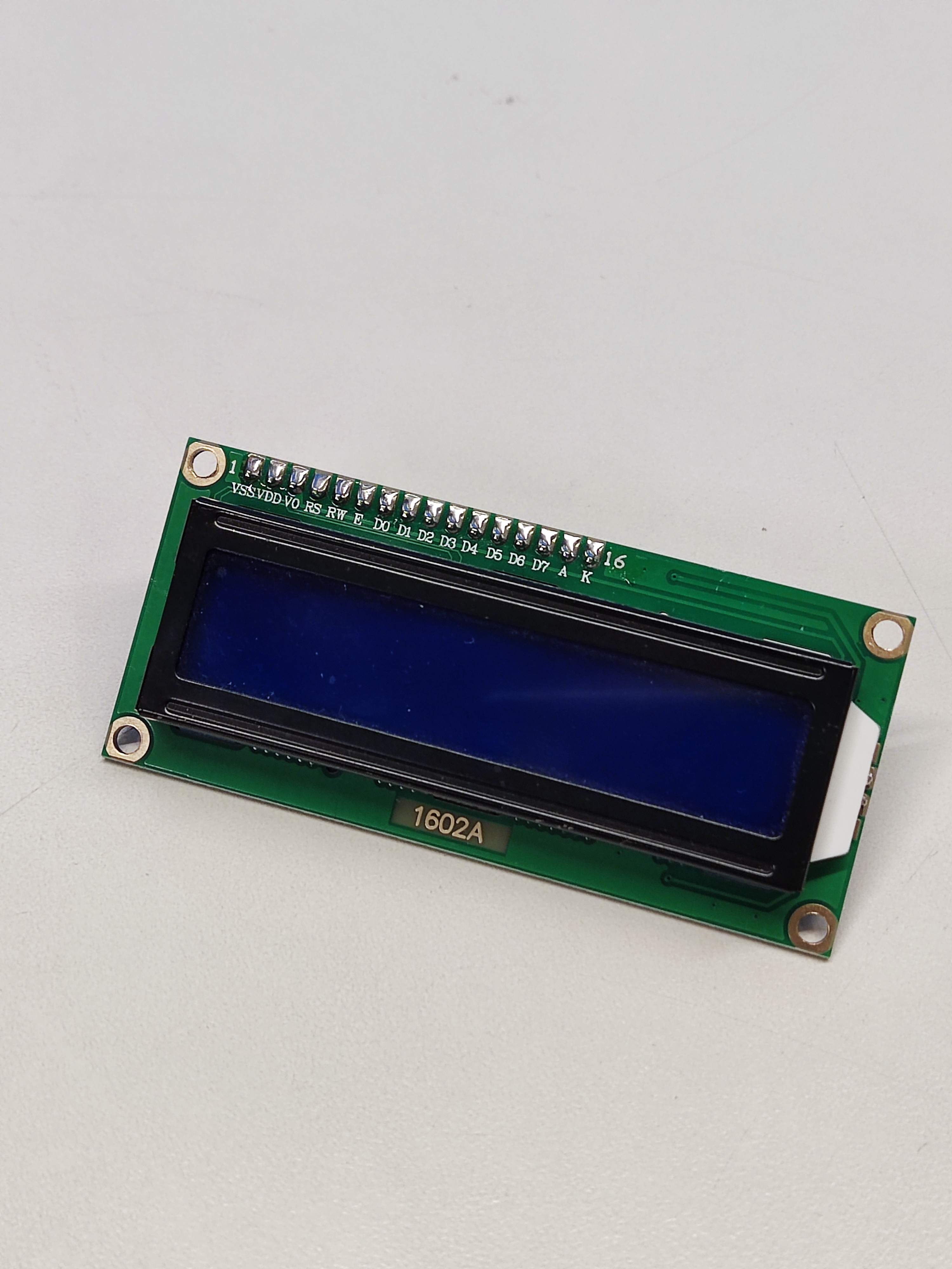
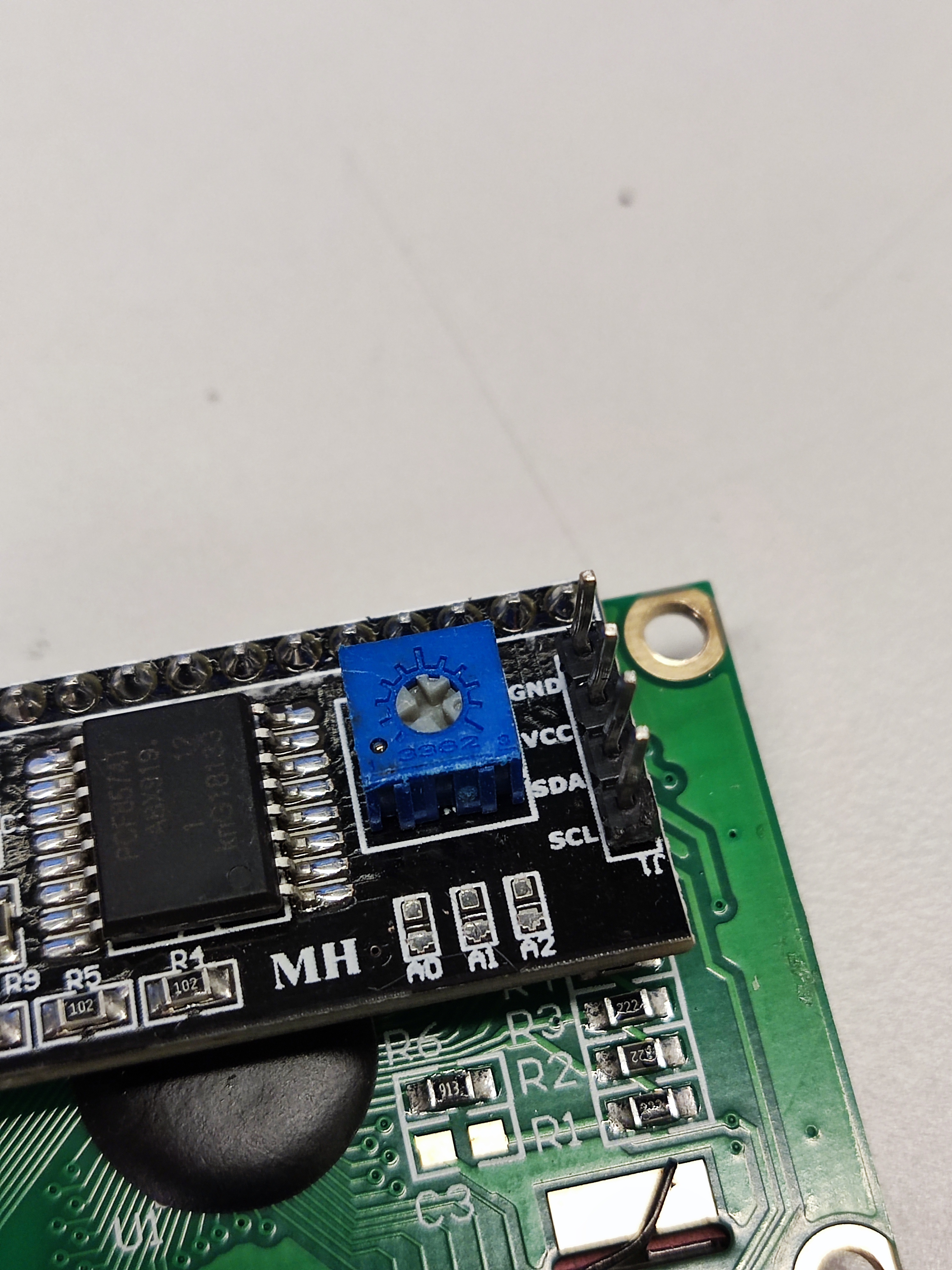
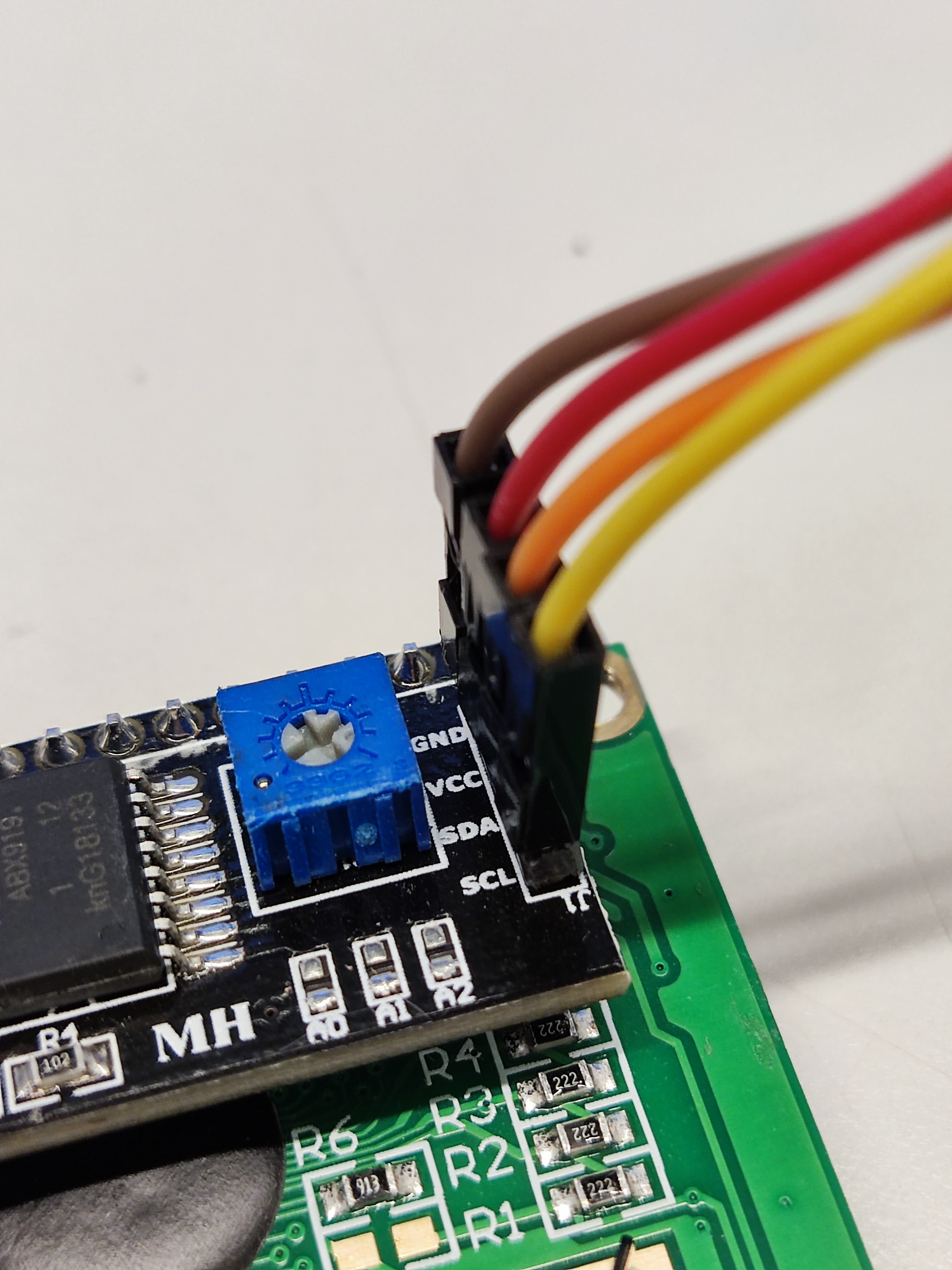
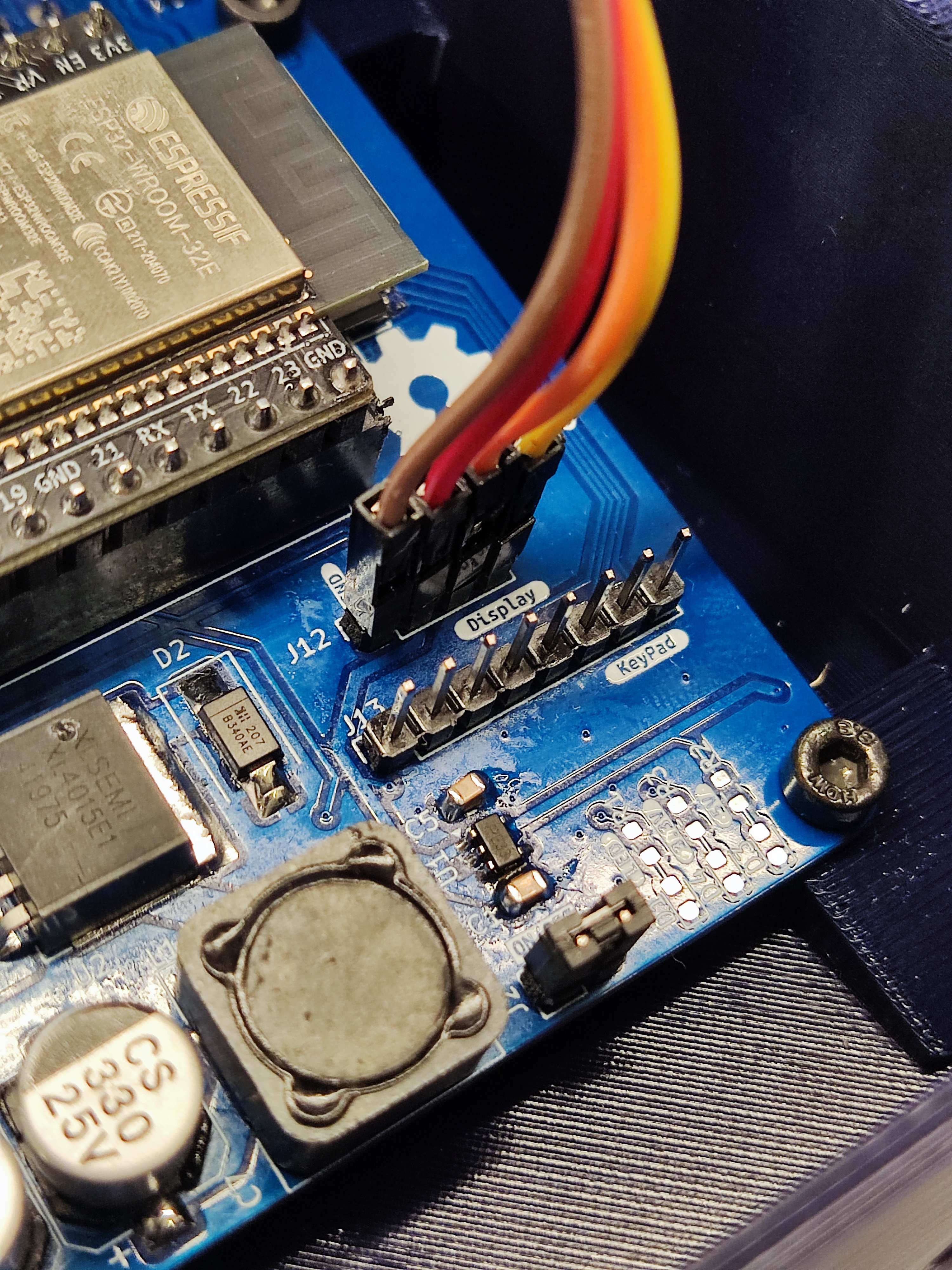
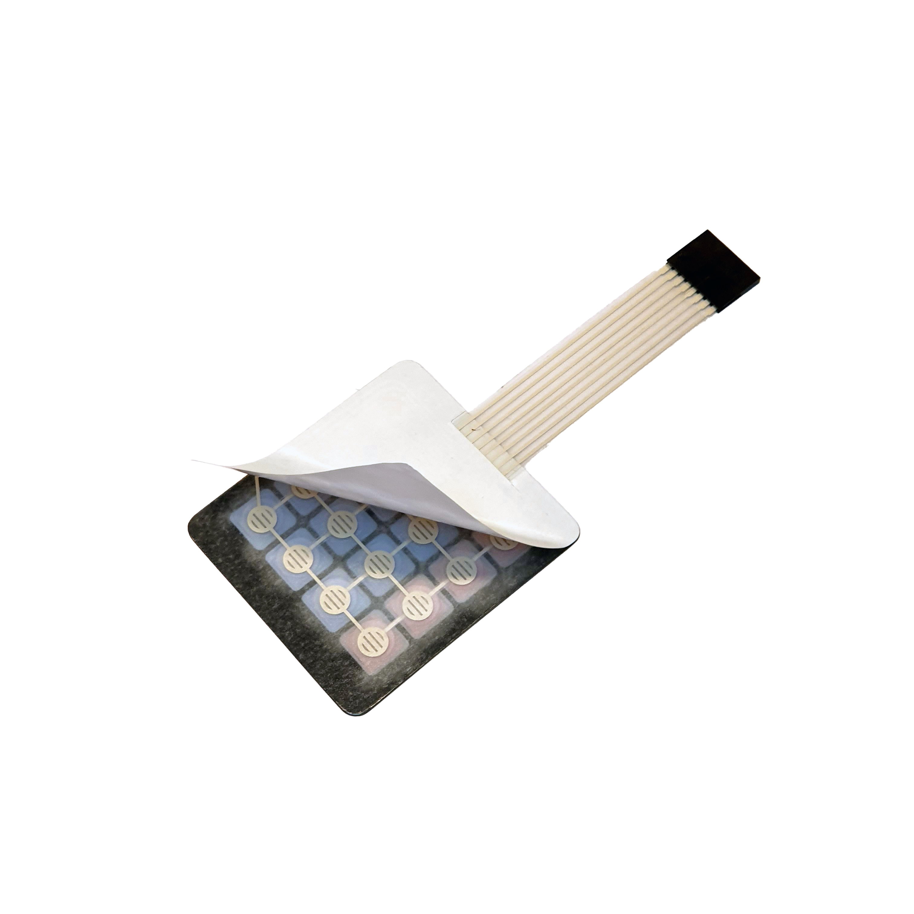
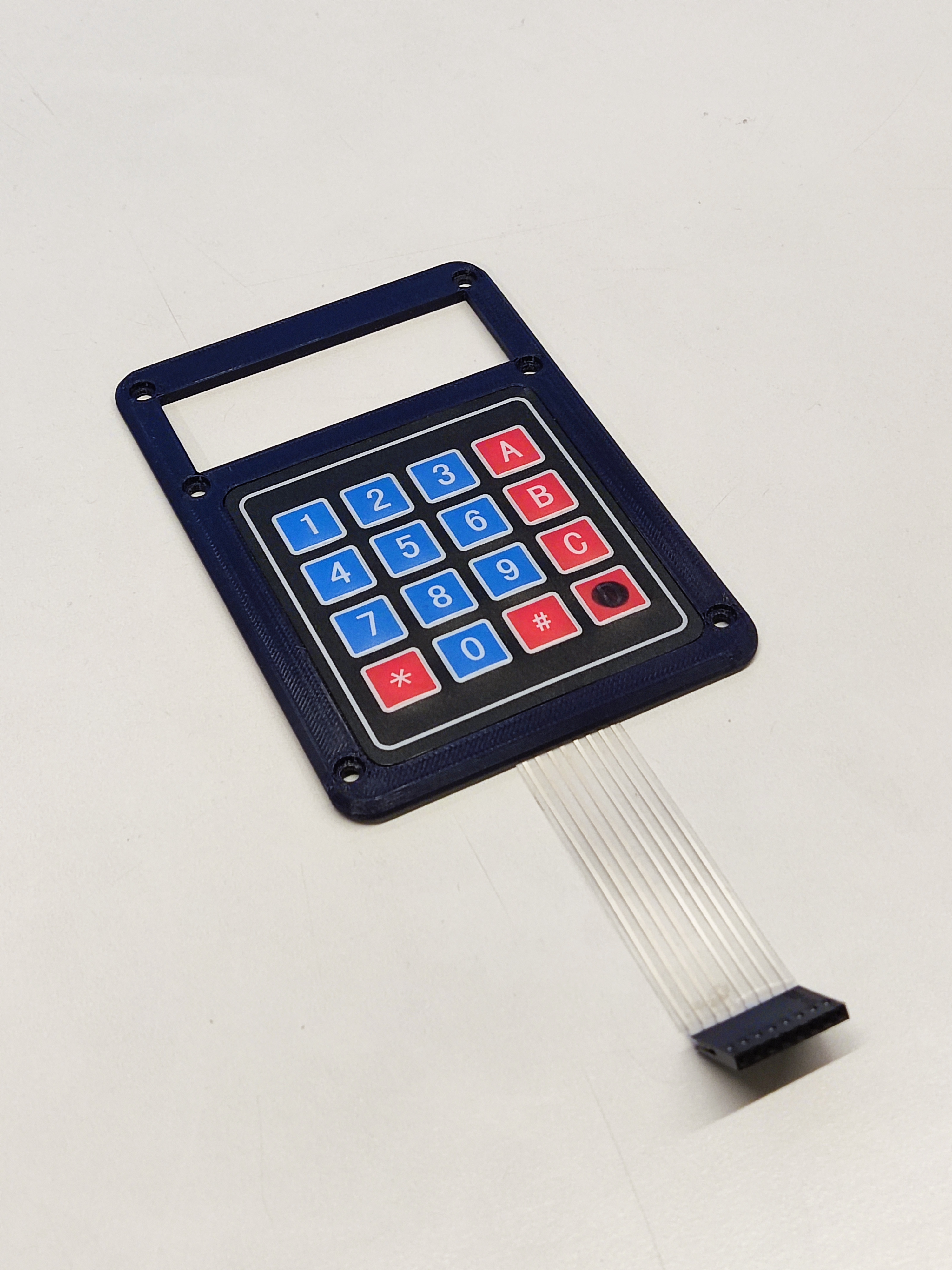
Take the membrane 4x4 keypad and peel off the backing, ensuring that all the paper is removed.
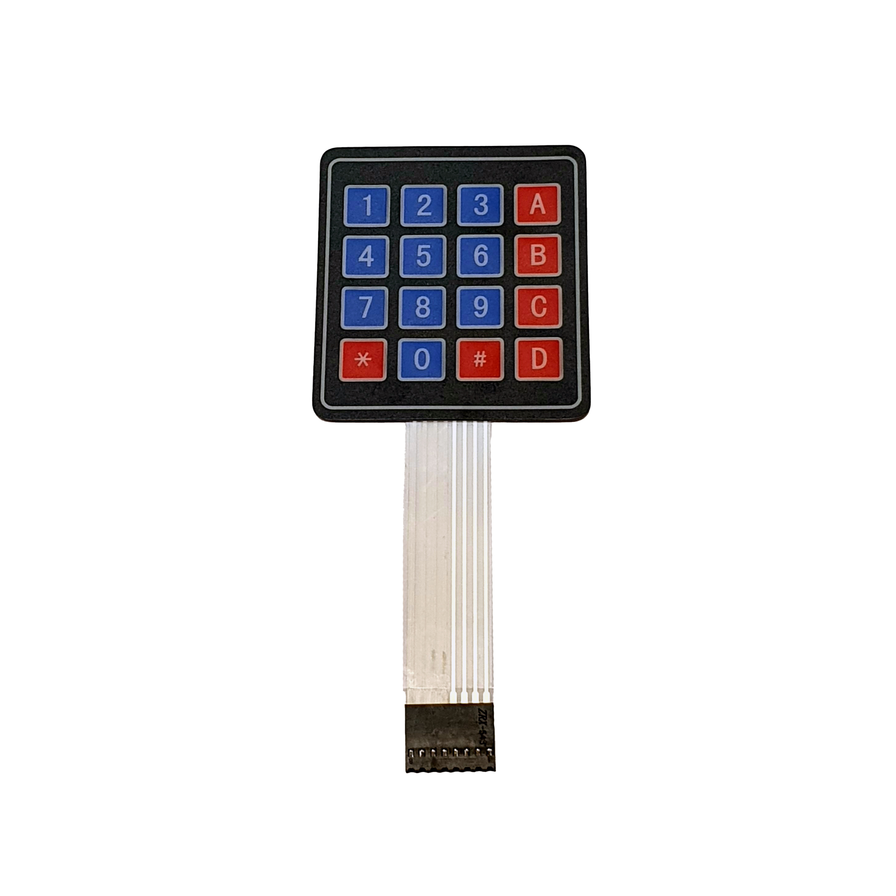
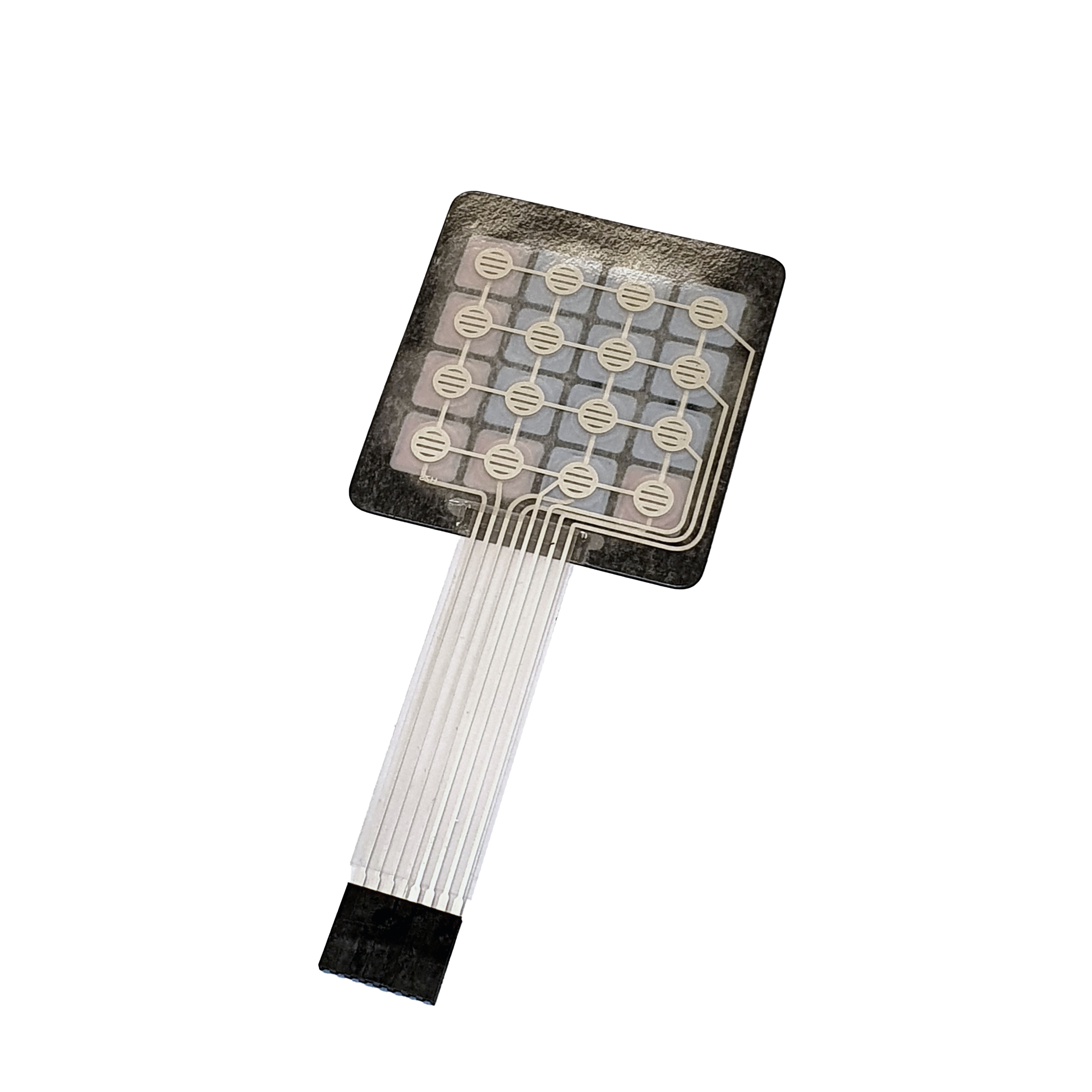
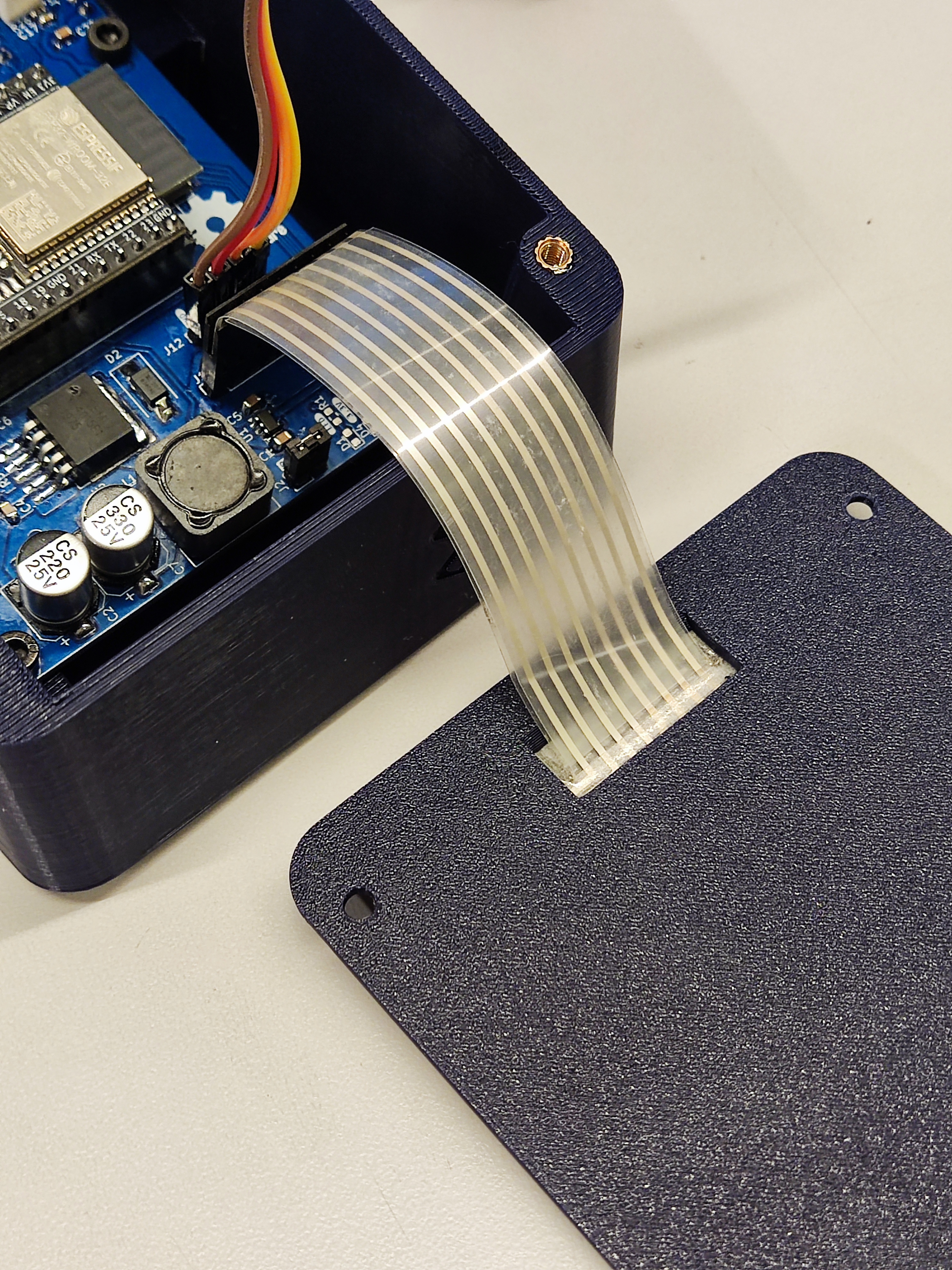
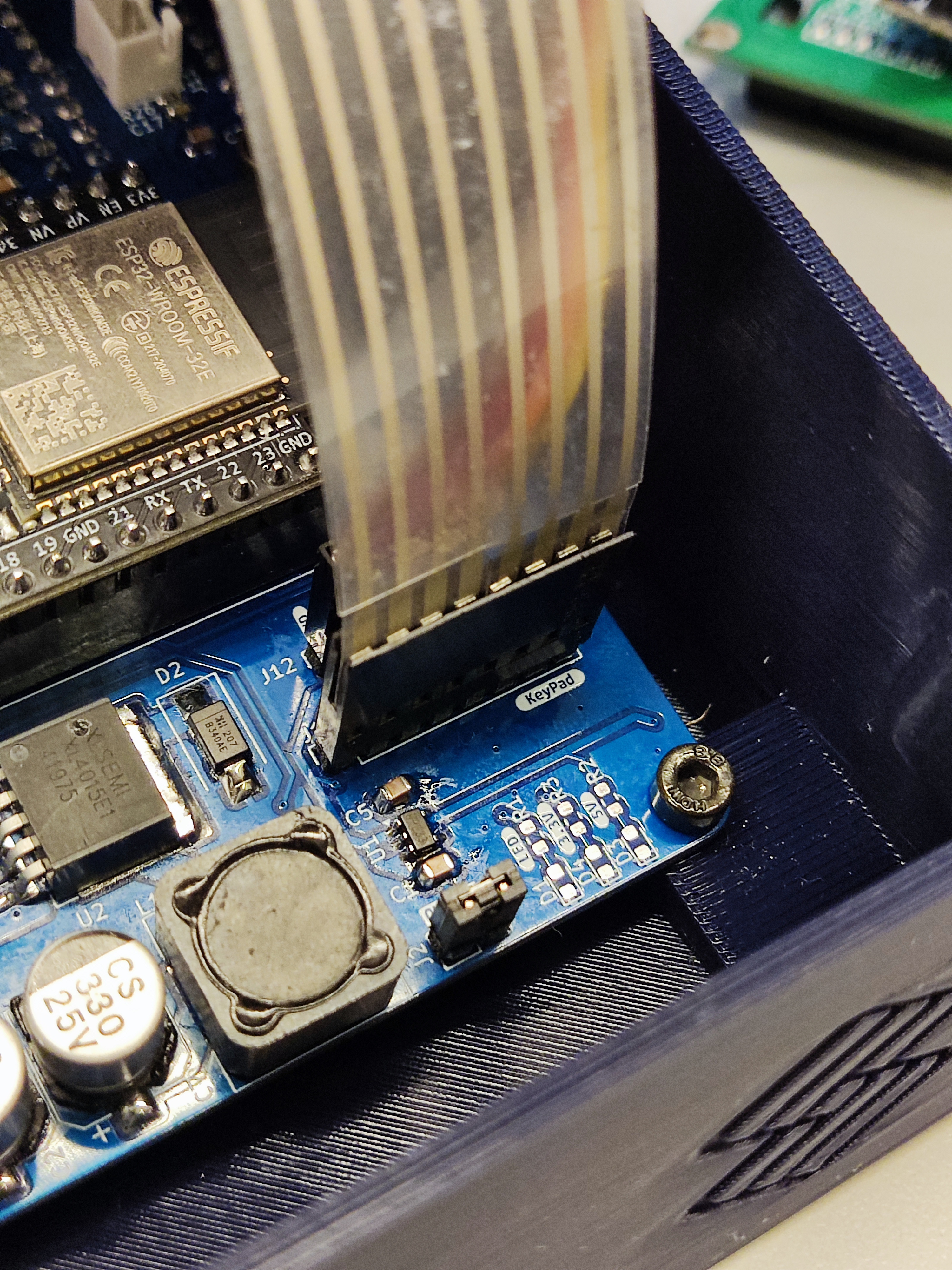
Pass the cables through the hole on the lid and securely attach the membrane 4x4 keypad in place. Then, connect the front panel to the keypad pins on the PCB.
Step 5: Place the LCD and front panel on the base
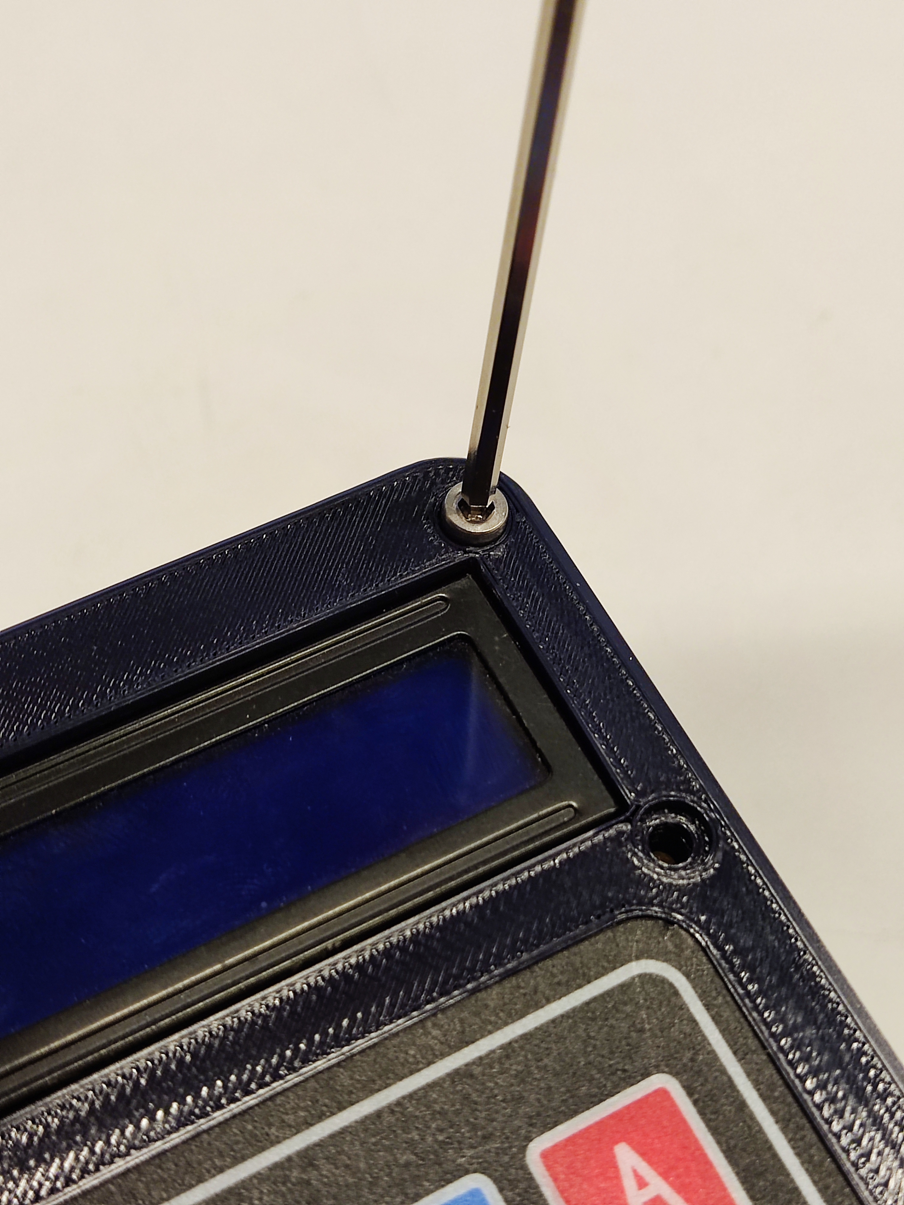
Now, place the LCD and front panel on the base to close the controller. Place first the spacer on the LCD, then place the LCD on the base and align its holes with the base holes. Take the front panel and place it on top of the LCD, aligning its holes with the LCD holes and the base holes. Secure the front panel to the base using six M3 10mm screws. Start by tightening the screws partially in a cross-diagonal pattern, then fully tighten them.
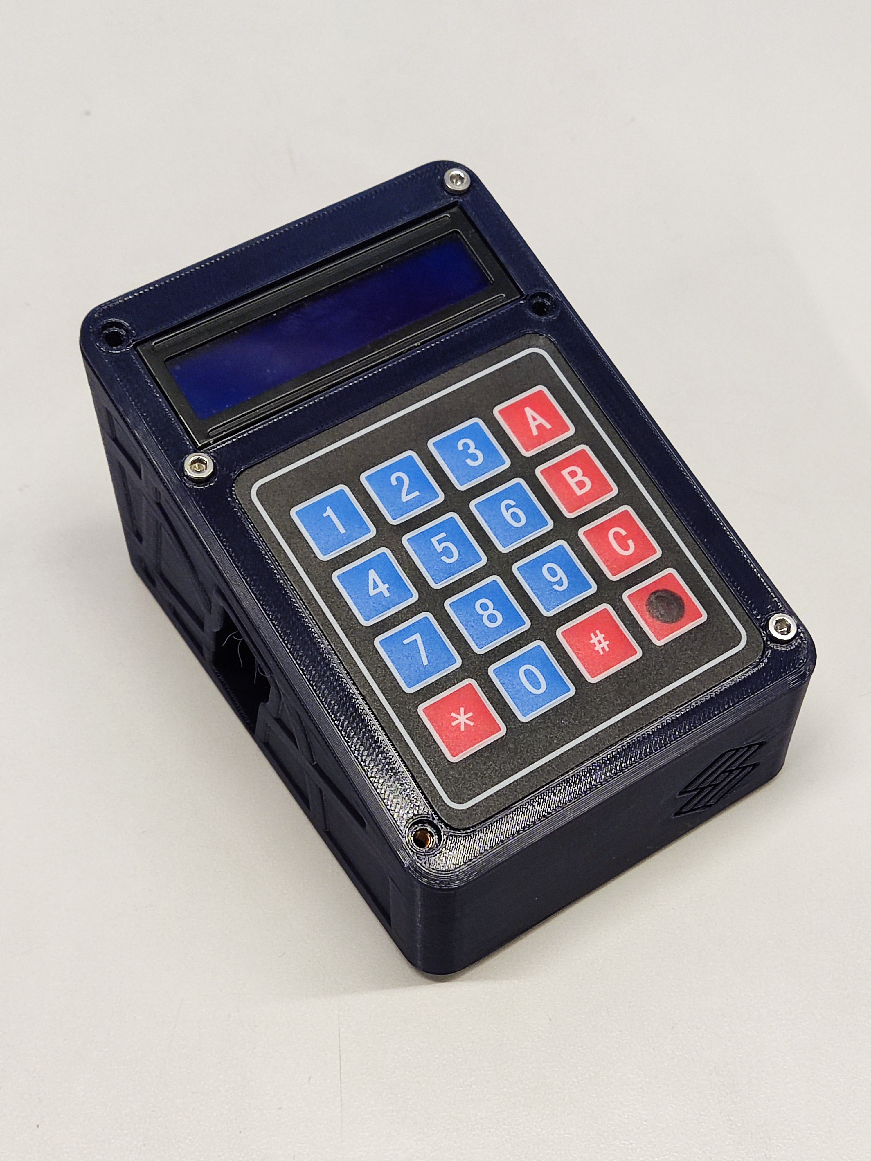
Well done! The controller is now assembled. It's time to flash the firmware.